Theoretical Analysis of the Influence of the Refractive Index on Electromagnetic Wave Propagating through Manganese Sulphide [MnS]
The theoretical analysis of the Electromagnetic wave propagation through chemically bath deposited manganese sulphide thin film and optical properties were studied using beam propagation technique in which a scalar wave is propagated through the material thin film deposited on a substrate with the assumption that the refractive index of the medium has homogenous reference refractive index reference term, nref and a perturbed refractive index term, representing the deposited thin film medium is presented in this work. These are substituted into a defined scalar wave equation in which the appropriate Green’s Function was defined on it and solved using series solution technique in conjunction with Born approximation method in order to obtain a model equation of wave propagating through the thin film. This was transformed to Voltera equation and used in computing the propagated field for different input regions of the field wavelength such as ultraviolet, visible and infrared region respectively during which the influence of the influence of the refractive index on the propagating wave through the thin film was considered. The results obtained from the computed field were used in turn to compute the band gaps and optical properties of the thin film.
Introduction
Manganese (II) sulfide (MnS) is a p-type semiconductor with a direct and wide band gap (Eg = ~2.05eV to2.95 eV) [1] with the absorbance and reflectance having unique behavior within 0-400nm Investigation Paper wavelength [2, 3, 4] and undergoes a transition to an antiferromagnetically (AFM) ordered phase below room temperature [5]. These features attracted interest for the potential applications of nanosized MnS in the field of short wavelength optoelectronics [6, 7, 8] or as a photoluminescent component [9], photo reduction catalysts [10], and contrast agent for magnetic resonance imaging (MRI) [11, 12]. The optical properties of MnS have also raised considerable interest in photobiology since it is deemed to have played a key role (along with ZnS in mixed haloes formed around primeval sub-aerial hot springs) in the prebiotic photosynthesis development. More recently, interesting energy-related applications have been demonstrated, where MnS was employed as an electrode material in Li-ion batteries [13, 14, 15] and as a supercapacitor material [16, 17]. These interesting properties and promising applications have raised considerable attention and research on small MnS particles that has been known to exist in three phases.
Three polymorphs (α, β, and γ) of MnS are known, and their crystal structure is distinct and can easily be differentiated. In the cubic rock-salt α-MnS structure, sulfide anions an expanded fcc lattice, and the manganese cations occupy all octahedral sites. The metastable form β-MnS has the cubic zincblende structure. Similarly to α- MnS, β-MnS comprises an expanded fcc lattice of S2−anions, but in this polymorph, the Mn2+ cations reside on half of the tetrahedral sites. Structurally, the cubic α- phase is stable at room temperature and also reasonably stable at all temperature [18, 19]. Finally-MnS and γ-MnS has the hexagonal wurtzite structure, based on a slightly compressed (c/a = 1.618) hcp lattice of sulfide anions with manganese cations occupying half of the tetrahedral sites can be grown at low temperature but they easily transform to the more stable α-phase above 200°C. The polymorphs have similar but unequal physical properties; for instance, all the three forms of MnS undergo transition to an AFM ordered structure [20], but the transition temperature varies from TN ~80 K for γ-MnS to ~100 K for β-MnS and 154 K for α-MnS [8].
Many techniques have been used to grow the thin film such as Chemical Bath, [21, 22] Although the process of growth and growth mechanism is not our main focus in this work but rather the mechanism involved in the process of characterization of the film in order to determine the applicability of the film which centers more on the way electromagnetic wave behaves as it propagates through the material we still need to high light the chemical bath growth technique which was the method used to grow the thin film we analyzed. This forms the inclination that brought about the use of wave propagation since the response by the material medium to the wave propagating through it is the determinant. Our method here involves propagating an input field over a small distance through the thin film medium and then iterating the computation over and over through the Ugwu EI. Theoretical Analysis of the Influence of the Refractive Index on Electromagnetic Wave Propagating through Manganese Sulphide [MnS]. Nanomed Nanotechnol 2018, 3(4): 000153.
propagation distance using Lippmann-Schwinger equation and its counterpart, Dyson’s equation [23].
Various tools have been employed in studying and computing beam or field propagation in a medium with variation of small refractive index [24, 25] some researchers had employed beam propagation method based on diagonalization of the Hermetician operator that generates the solution of the Helmholtz equation in media with real refractive indices [26] while some had used 2x2 propagation matrix formalism for finding the obliquely propagated electromagnetic fields in layered inhomogeneous un-axial structure [27]. Structure such as optical fibres, optical wave guides in the presence of electro-optical perturbation [28, 29]. However, earlier before the, work had been going on veraciously on study of wave propagation in a stratified media, plasma and ionosphere [30]. Van Roey in his work derived a general beampr0pagation relation in a number of specific cases along with the extensive simulation of wave propagation in variety of material medium. The effect of variation of refractive index of FeS2, influence of dielectric function and conductivity of thin film material on propagating wave through its medium had also been carried out [24, 31, 32]. A close look on the concept made it clear to recognize the importance of the effect of the refractive index of the medium in the reality of the two velocity components that normally give rise to phase and group refractive indices as considered study of wave propagation [33, 34]. More complicated work are being embarked upon on the study of wave propagation through a modeled thin with dielectric perturbation in which W.K.B approximation in conjunction with numerical approach were used .In this work, we make use of theoretical concept to study the influence of refractive index on wave propagating through Manganese Sulphide thin film medium and use the approach to analyze the optical properties of the thin film circumventing the use of experiment that always involve a huge sum of fund for its growth and analysis coupled with lack of needed and required equipment for such work since research in nanoscience is the order of the day due to its technological applications.
In this our method here we involves the concept of propagation of an input field over a small distance through the thin film medium and then iterating the computation over and over through the propagation distance using Lippmann-Schwinger equation and its counterpart, Dyson’s equation. In this case, we first derived Lippmann-Schwinger equation using a specific Hamiltonian from where the field function ψk (z) was Copyright© Ugwu EI.
obtained using a specific Hamiltonian from where the field function ψk (z) and write it as Voltera equation from where the solution for Green’s value is sought using the boundary condition ( ,0) G(z,z ) G z = with which absorption characteristics is sought within the wavelength ultraviolet, visible and infra-red regions of electromagnetic wave spectrum aimed at analyzing the influence of the refractive index of the material thin film on the propagated wave from the theoretical solution.
Experimental Procedure of Growing Thin Films
Experimentally, glass slides are used as substrate in growing the films though they were first of all washed using soap solution and subsequently kept in hot chromic acid and then cleaned with deionized water followed by rinsing in acetone. Finally, the substrates were ultrasonically cleaned with deionized water for 10 min and wiped with acetone and stored in a hot oven at 40°C. Typically, 20ml of 1M manganese acetate tetrahydrate (C4H6MnO4·4H2O) and 4 ml of 7.4 M triethanolamine (C6H15NO3) (TEA) were vigorously mixed in 100 ml glass beaker for 5 min. After that, 20 ml of 1.5 M ammonia solution (NH4OH) was added to the solution and further stirred for 10 min. Then under constant stirring, 0.4ml of hydrazine hydrate (H4N2H2O) (80%) solution was mixed followed by 20 ml of 1.4 M thioacetamide (C2H5NS) and the solution was stirred for 10 min. The final solution was made 75 ml by adding double distilled water. The pH of the bath solution was found to be 11. The already cleaned micro-scope glass slides were used as substrates. The glass slide substrate was immersed in the prepared bath solution and kept vertical in the beaker for thin film deposition. The deposition was done at room temperature. After 6 h, the glass slide was removed, rinsed with double distilled water and allowed air drying. Many trials were conducted to optimize the deposition parameters to obtain a good quality MnS thin film. The resultant films were homogeneous and well adhered to the substrate with mirror like surface. The deposited glass beaker for 5 min. After that, 20 ml of 1.5 M ammonia solution (NH4OH) was added to the solution and further stirred for 10 min. Then under constant stirring, 0.4ml of hydrazine hydrate (H4N2H2O) (80%) solution was mixed followed by 20 ml of 1.4 M thioacetamide (C2H5NS) and the solution was stirred for 10 min. The final solution was made 75 ml by adding double distilled water. The pH of the bath solution was found to be 11. The already cleaned micro-scope glass slides were used as substrates. The glass slide substrate was immersed in the prepared bath Ugwu EI. Theoretical Analysis of the Influence of the Refractive Index on Electromagnetic Wave Propagating through Manganese Sulphide [MnS]. Nanomed Nanotechnol 2018, 3(4): 000153.
solution and kept vertical in the beaker for thin film deposition. The deposition was done at room temperature. After 6 h, the glass slide was removed, rinsed with double distilled water and allowed air drying. Many trials were conducted to optimize the deposition parameters to obtain a good quality MnS thin film. The resultant films were homogeneous and well adhered to the substrate with mirror like surface.
Theoretical and Analytical Frame Work
In this concept, we start by considering scalar wave equation as given below that defines general expression for wave propagating through an arbitrary medium.
$$ \nabla^ {2} \psi (r) + \omega^ {2} \varepsilon_ {o} \mu_ {o} \psi (r) = 0 \tag {1} $$ But however, in this equation we introduce a perturbation that defines refractive index in thin film medium and reference refractive index nref representing a space without thin film and a refractive index in the thin film medium Dnp (z) where the thin film is as shown the Figure 1 below.
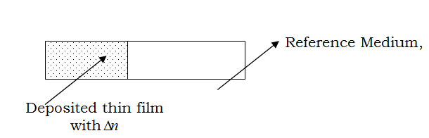
Figure 1: Deposited manganese Sulphide thin film Model on a glass substrate where the Refractive index function as defined in equation (1) $$ n _ {p} = n _ {r e f} + \Delta n (z) \tag {1)b} $$ The wave equation relating our model can be written as $$ \nabla^ {2} \psi (z) = - k ^ {2} n _ {r e f} ^ {2} \psi (z) - k ^ {2} \Delta n \psi (z) \tag {2} $$ For us to get a meaningful solution to the problem, second term on the right side would be considered to be zero, such that $$ \nabla^ {2} \psi (z) + k ^ {2} n ^ {2} \psi (z) = 0 \tag {3} $$
If the field value for z= z0 is known for radiation at z ψ ∂ infinity, the propagating field, ψ and its gradient ∂ Copyright© Ugwu EI.
can be determined for all the values of the propagating distant, $z$ by means of an operator $A^\dagger$ which now transforms our expression as
$$\frac{\partial \psi_1}{\partial z} = A^\dagger \psi(z) \text{ and } \frac{\partial \psi_2}{\partial z} = B^\dagger \psi(z)$$ (4)
Where the operator, $A^\dagger$ and $B^\dagger$ signify the transverse coordinate of the field in first and second terms in (4).
The Green’s function for our problem can be deduced by first of all constructing the Green’s function which involves the solutions of the homogeneous equation (3) that will enable us write the Dyson’s equation as thus
$$\psi(z, z') = \int_0^{z'} G(z, z') V(z') \psi(z') dz'$$ (5)
Given $G(z, z')$ the Green’s function specified by;
$$G(z, z') = \frac{2}{z} \sum_{n=1}^{\infty} \frac{\sin(n\pi z'/z)}{\gamma^2 - \frac{n^2\pi^2}{z^2}}$$ (6)
$$V(z) = -\gamma^2 \Delta n_p(z) = -\gamma^2 \left(n_p(z) - n_{ref}\right)$$ (7)
Linearizing $n(z)$ as follows;
$$n(z) \approx n_0 + kz + o(z^2),$$ (8)
We neglect higher order terms as we are dealing with thin film,
Where $\mathcal{E}_0$ and $k$ are constants,
$$V(z) = -\gamma^2 \Delta n(z) = -\gamma^2 \left(n(z) - n_{ref}\right)$$
$$= -\gamma^2 \left(n_0 - n_{ref} + kz\right)$$
$$= -\gamma^2 \left(n' + kz\right)$$ (9)
Furthermore, we have $\psi(z') = \sin\left(\frac{2\pi}{\lambda} z'\right)$
Hence the integral becomes;
$$\psi(z) = \int_0^{z'} \frac{2}{z} \sum_{n=1}^{\infty} \frac{\sin(n\pi z'/z)}{\gamma^2 - \frac{n^2\pi^2}{z^2}} \left(-\gamma^2 \left(n' + kz'\right)\right) \sin\left(\frac{2\pi}{\lambda} z'\right) dz'$$ (10)
Hence we replaced $\mathcal{E}'$ by $\mathcal{E}$ and write
$$I(z, z') = -\gamma^2 \int_0^{z'} \frac{2}{z} \sum_{n=1}^{\infty} \frac{\sin(n\pi z'/z)}{\gamma^2 - \frac{n^2\pi^2}{z^2}} \left(n + kz'\right) \sin\left(\frac{2\pi}{\lambda} z'\right) dz'$$ (11)
In which we obtain the integral as
Nanomedicine & Nanotechnology Open Access
$$\psi(z, z') = -\frac{2}{z} \sum_{n=1}^{\infty} \frac{\gamma^2}{\left(\gamma^2 - \frac{n^2 \pi^2}{z^2}\right)} \int_{0}^{z'} \sin\left(m \pi z'/z\right)\left(n+kz'\right) \sin\left(\frac{2 \pi}{\lambda} z'\right) dz'$$ (12)
$$G(z, z')$$
$$= -\frac{2}{z} \sum_{n=1}^{\infty} \frac{\gamma^2}{\left(\gamma^2 - \frac{m^2 \pi^2}{z^2}\right)} \times$$
$$\left\{ \begin{array}{l} n \pi \left\{m^3 \lambda^3 \sin\left[\frac{(2z+m \lambda) \pi z'}{\lambda z}\right] - 2 \varepsilon \pi m^2 \lambda^2 z \sin\left[\frac{(2z+m \lambda) \pi z'}{\lambda z}\right] - 4 \varepsilon \pi n \lambda z^2 \sin\left[\frac{(2z+n \lambda) \pi z'}{\lambda z}\right] \\ \pi^2 \left(4z^2 - m^2 \lambda^2\right)^2 \\ 2 n \pi m^2 \lambda^2 z \sin\left[\frac{(2z-m \lambda) \pi z'}{\lambda z}\right] - 4 k \pi m \lambda z^2 \sin\left[\frac{(2z-m \lambda) \pi z'}{\lambda z}\right] - 8 m \pi z^3 \sin\left[\frac{(2z-m \lambda) \pi z'}{\lambda z}\right] \\ \pi^2 \left(4z^2 - m^2 \lambda^2\right)^2 \\ 8 k \pi z^3 z' \sin\left[\frac{(2z+m \lambda) \pi z'}{\lambda z}\right] - 8 k \pi z^3 z' \sin\left[\frac{(2z-m \lambda) \pi z'}{\lambda z}\right] - 4 k m \lambda^2 z^2 \cos\left[\frac{(2z+m \lambda) \pi z'}{\lambda z}\right] \\ \pi^2 \left(4z^2 - m^2 \lambda^2\right)^2 \\ - 4 n \pi m \lambda z^2 \sin\left[\frac{(2z-m \lambda) \pi z'}{\lambda z}\right] + k m^2 \lambda^3 z \cos\left[\frac{(2z+m \lambda) \pi z'}{\lambda z}\right] + n \pi m^3 \lambda^3 \sin\left[\frac{(2z-m \lambda) \pi z'}{\lambda z}\right] \\ \pi^2 \left(4z^2 - m^2 \lambda^2\right)^2 \\ k \pi m^3 \lambda^3 z' \sin\left[\frac{(2z+m \lambda) \pi z'}{\lambda z}\right] + 4 kz^3 \lambda \cos\left[\frac{(2z+m \lambda) \pi z'}{\lambda z}\right] - 2 k \pi m^2 \lambda^2 z' z \sin\left[\frac{(2z+m \lambda) \pi z'}{\lambda z}\right] \\ \pi^2 \left(4z^2 - n^2 \lambda^2\right)^2 \\ - kn^2 \lambda^3 z \cos\left[\frac{(2z-m \lambda) \pi z'}{\lambda z}\right] + 8 \varepsilon \pi z^3 \sin\left[\frac{(2z+m \lambda) \pi z'}{\lambda z}\right] - 4 kz^2 \lambda^2 n \cos\left[\frac{(2z-m \lambda) \pi z'}{\lambda z}\right] \\ \pi^2 \left(4z^2 - m^2 \lambda^2\right)^2 \\ - 4 kz^3 \lambda \cos\left[\frac{(2z-m \lambda) \pi z'}{\lambda z}\right] - 4 k \pi z^2 \lambda m z' \sin\left[\frac{(2z+m \lambda) \pi z'}{\lambda z}\right] - 4 k m \lambda^3 z^3 \\ \pi^2 \left(4z^2 - m^2 \lambda^2\right)^2 \end{array} \right$$ (13)
Analytically, the Green’s function could be obtained by using Green’s function series expansion solution technique with boundary condition that
$$G(z, 0) = G(z, z')$$ (14)
As the right hand vanishes at the end of the interval $(0, z)$ which makes possible to expand the function in a suitably chosen orthogonal functions such as Fourier series [24].
The solution of the inhomogeneous part of the film becomes
$$\psi(z, z') = \int_{0}^{z} G(z, z') f(z') dz'$$ (15)
Where $f(z') = k \Delta n^2 \psi(z')$ (16)
The series solution of the problem becomes
$$G(z, z') = \frac{2z}{\pi^2} \sum_{m=1}^{\infty} \frac{1}{m} \sin\left(\frac{m\pi z'}{z}\right) \int f(z') \sin\left(\frac{m\pi z'}{z}\right) dz'$$ (16)
Assuming $\Delta n$ to be periodic, we can write
$$\rho_m = \int_{0}^{a} f(z') \sin\left(\frac{m\pi z'}{z}\right) dz'$$ (17)
$$\psi(z, z') = \frac{2z}{\pi^2} \sum_{m=1}^{\infty} \frac{1}{m^2} \rho_m \sin\left(\frac{m\pi z'}{z}\right)$$ (18)
Analysis of the Influence of Refractive Index on the Propagating Wave
Considering the wave to be propagating through the film towards the increasing $z$ with no paraxiality, we split the increasing wave into two parts with $\psi_1$ being regarded as the wave propagating from higher refractive index region of the thin film and $\psi_2$ as the part propagating through the less refractive index region respectively. The total sum of the propagating wave in the medium becomes
$$\psi = \psi_1 + \psi_2$$ (19)
This could be written as
$$\frac{\partial \psi}{\partial z} = A^T \psi_1 + B^T \psi_2$$ (20)
Analytically, equation (20) is an important approximation, though it appears to restrict the use of beam propagation technique in the study of the influence of the reflected wave on the forward propagating one in a structured thin film material except where there is a variation in the refractive index as a function of the propagating distant in which case the reflected wave add up coherently to the propagating wave and since the Green’s function as obtained in our formalism satisfies
$$\left[ \left( \frac{\partial^2}{\partial z^2} + \frac{\partial^2}{\partial z'^2} \right) \Delta n(z, z') \right] G(z, z') = \delta(z - z') \delta(z' - z),$$ (21)
at the boundary source point in conjunction with the impedance boundary condition
$$G(z, z') + \beta_o \frac{\partial G(z, z')}{\partial n}$$ (22)
where $\beta_o = \frac{iR_s}{kR_o}$ and $R_o = \left[ \frac{\mu_o}{\varepsilon_o} \right]^{1/2}$ and $R_s$ and $R_o$ signifies the characteristic impedance offered by the thin film medium to the propagating wave and that of the free space impedance respectively which is given by
$$R_s = \frac{R_o}{n} \left[ 1 - \frac{1}{n^2} \right]$$ (23)
For every given wave of wavelength, $\lambda$ propagating through the thin film medium of refractive index $n$, the impedance is expressed as in equation (23). With the knowledge of the impedance, the absorption co-efficient of the propagating wave is computed and in turn used for further application.
This is the situation that enabled us to consider it valid in the computation of the absorption co-efficient that was applied in computation of the band gap, and other optical properties of the thin film.
In all use we considered in analysis the wavelength within $\lambda = 250\text{nm}$ to 1200\text{nm}
From the equation, it is obvious that $(\psi(z))$ tends to 0 as the dielectric constant $\varepsilon' \to \infty$.
Therefore for fixed values of other parameters, the resultant solution can be approximated to any number of terms as may be required in relation to wave propagation terms.
This is used to obtain the absorption co-efficient using α
= exp o I I z (24)
$$ = \frac {1}{z} \ln \left(\frac {1}{T}\right) $$
1 1 α In z T
known as Lamber-Beer- Bouguer law and the transmittance is obtained from ( )
2 $$ T = \frac {\left(1 - R\right) ^ {2} \exp - \alpha t}{1 - R ^ {2} \exp - 2 \alpha t} $$ (25) The reflectance is also deduced in terms of absorption coefficient as ( ) 1 1 exp( ) exp α α $$ 1 \pm \left(1 - \exp (- \alpha t)\right) + e $$ t t R (26) α + −
1 exp( ) t While from the values of the reflectance the refractive index of the film which is wavelength dependent can be obtained from the equation ( )( ) ( ) $$ v = \frac {\left(R + 1\right) + \left(3 R ^ {2} + 1 0 R - 3\right)}{2 (R - 1)} $$
2 1 3 10 3 R R R n (27) [20]
−
2 1 R
The absorption coefficient is used in equation (25) to plot the graph from where the band gap of the film should be deduced ( )
2 $$ \left(\alpha h \nu\right) ^ {2} = A \left[ h \nu - E _ {g} \right] $$
[40] (28)
Result/Discussion
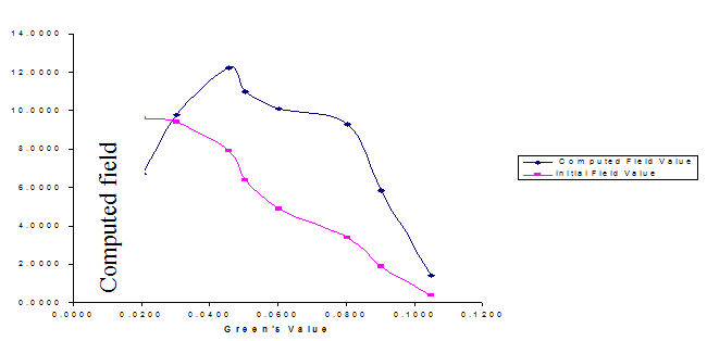
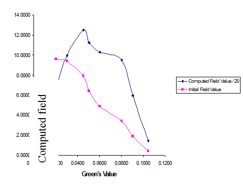
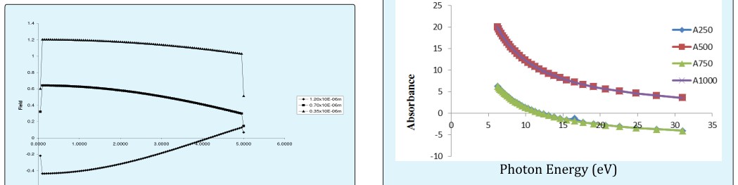
The computed field ψ as a function of Green’ values, G were presented in Figures 2-4 where it is seen that the optimum value of the field was located at the point where the Green’s value is 0.45 in all the graphs for the UV, Visible and Infra-red region of electromagnetic wave. This made it more paramount for us to use a constant value of the green’s value in subsequent computation of other parameters where G was needed especially in analyzing the wave profiles as it propagates through the thin film medium as shown in Figures 5-7 in which it is clearly seen that UV exhibited a negative value of the field profile while visible and infrared appeared on the positive value of the field. Specifically, the wave profiles varies with the propagation distant where it is seen that visible and infrared have the highest field within 0.1µm with a decrease on the value of the field as the propagation distant increased to 0.50µm.On the other hands, UV experienced a minimum value within 0.10µm experiencing the highest field value at 4.50µm of the propagation distant. The of the behavior profiles in this manner probably seems to be reflected on the optical Ugwu EI. Theoretical Analysis of the Influence of the Refractive Index on Electromagnetic Wave Propagating through Manganese Sulphide [MnS]. Nanomed Nanotechnol 2018, 3(4): 000153.
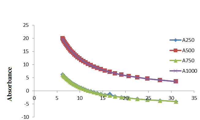
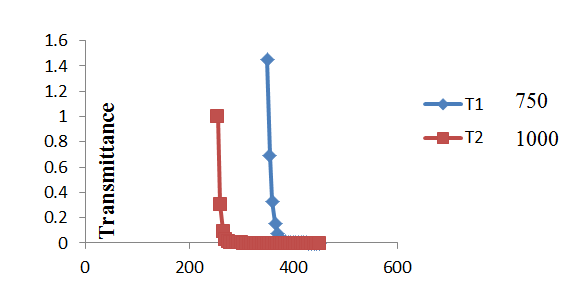
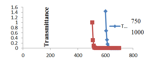
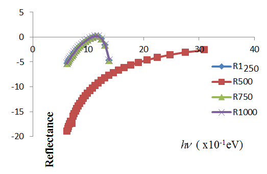
response of the thin film to electromagnetic wave propagation through it. The absorbance and transmittance are as shown in Figures 8-10 where was observed that the absorbance profile for the film in UV and blue regions appears negative; the reflectance is negative all through within all the regions as shown in Figure 11. The transmittance exhibited selective behavior within some windows as seen in Figure 10 and 11. The band gap values were obtained from extrapolated graphs of equation (20) which were plotted according to wavelengths within the three regions considered in this work which implies that the band gap was marched to a particular wavelength as shown in Figure 12.
() () () () () λ λ λ
= $$ \lambda = 2 5 0 n m \quad 2. 7 7 e V (c) \lambda = 7 5 0 n m \quad 2. 2 4 e V \quad (e) \lambda = 1 2 0 0 n m \quad 2. 0 8 e $$ a nm eV c nm eV e nm eV λ λ $$ \lambda = 5 0 0 n m \quad 2. 3 3 e V (d) \lambda = 1 0 0 0 n m \quad 2. 1 9 e $$ b nm eV d nm eV The average of the band gap for all the wavelength is 2.68eV
Copyright© Ugwu EI.
Ugwu EI. Theoretical Analysis of the Influence of the Refractive Index on Electromagnetic Wave Propagating through Manganese Sulphide [MnS]. Nanomed Nanotechnol 2018, 3(4): 000153.
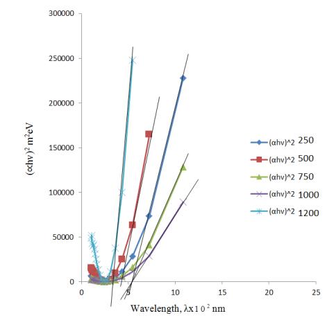
2 h αν of MnS as a function of wave length for 250nm.500nm, 750nm 1000nm and 1200nm.
Ugwu EI. Theoretical Analysis of the Influence of the Refractive Index on Electromagnetic Wave Propagating through Manganese Sulphide [MnS]. Nanomed Nanotechnol 2018, 3(4): 000153.
Conclusion
Here theoretical and analytical studies have been carried out on the influence of the refractive index on the electromagnetic wave propagation through MnS thin film with refractive index ,n where Green’ function and Lippmann-Schwinger equations played prominent role in the mathematical formalism in conjunction with Voltera equation. The computed Green’s values were used to analyze the behaviour of the wave profile and subsequently utilized in obtaining the absorption co- efficient that made it possible in computing the band gap and other optical parameters studied here in this work.
However there were clearly observed difference especially in the computed band gap as compared to experimentally deduced band gap of the thin film which is bound to be obvious because of some of the assumption that characterized the computation in which lattice dynamics and structures were ignored in the entire formalism. Such deviation also exists in the experimental characterization where the growth techniques, annealing and variation of complexing argents and doping influence the crystallinity of the entire film which invariably results variation in the properties of the thin films. The spectral reflectance of the thin film in this work manifested the same characteristic as showcased in the report of Umeri and Emumejaye, 2015 [3]. This appears as confirmation of the negative characteristic nature of the wave profile within the widow.
References
-
Anuar Kassim, Ho Soon M (2010) Deposition and Characterization of MnS Thin films by Chemical Bath Deposition Method. Int J of Chemistry Research 1(1): 1-5.
-
Adel Sedoa, Ramphal Sharma (2017) Studies and Characterization of Nanostructured MnS Thin film Prepared by Chemical Bath Deposition Technique. Intl J Pure and Appl Phy 13(2): 241-248.
-
Daniel-Umeri RA, Emumejaye K (2015) Optical and solid State Properties of MnS Thin film Deposited using CBD. Int J of Scientific Research 6(11): 657-663.
-
Ikhioya IL, Ugbo FC, Ijabor B, Okeghene (2018) Growth and Characterization of Manganese Sulphide Thin Films. Int j for Research in Appl and Natural Science 4(1): 1-9. Copyright© Ugwu EI.
-
Danielian A, Stevens KWH (1961) Exchange interactions in the polymorphic forms of MnS. Proceedings of the Physical Society 77(1): 124-128.
-
Tappero R, Darco P, Lichanot A (1997) Electronic structure of α-MnS (alabandite): An ab initio study. Chem Phys Lett 273(1-2): 83-90.
-
Hobbs D, Hafner J (1999) Magnetism and magneto- structural effects in transition-metal sulphides. J Phys Condens Matter 11(42): 8197-8222.
-
Kravtsova AN, Stekhin IE, Soldatov AV, Liu X, Fleet ME (2004) Electronic structure of MnS (M=Ca,Mg,Fe,Mn): X-ray absorption analysis. Phys Rev B 69(13).
-
Viswanath R, Naik HSB, Kumar GSY, Kumar PNP, Harish KN, et al. (2014) Luminescence properties of blue-red emitting multilayer coated single structure ZnS/MnS/ZnS nanocomposites. Spectrochim Acta A 125: 222-227.
-
Zhang XV, Martin ST, Friend CM, Schoonen MAA, Holland HD (2004) Mineral-assisted pathways in prebiotic synthesis: Photoelectrochemical reduction of carbon (+IV) by Manganese sulfide. J Am Chem Soc 126(36): 11247-11253.
-
Chilton HM, Jackets SC, Hinson WH, Ekstrand K (1984) Use of a paramagnetic substance, colloidal manganese sulfide, as an NMR contrasts material in rats. J Nucl Med 25(5): 604-607.
-
Meng J, Zhao Y, Li Z, Wang L, Tian Y (2016) Phase transfer preparation of ultrasmall MnS nanocrystals with a high performance MRI contrast agent. RSC Adv 6(9): 6878-6887.
-
Chilton HM, Jackets SC, Hinson WH, Ekstrand K (1984) Use of a Paramagnetic Substance, Colloidal Manganese Sulfide, as an NMR Contrast Material in Rats. J Nucl Med 25(5): 604-607.
-
Huarac BJ, Palomino J, Resto O, Wang J, Jadwisienczak WM, et al. (2014) Highly-crystalline γ-MnS nanosaws. RSC Adv 4(72): 3810-38110.
-
Lee SM, Lee JK, Kang YC (2014) Electrochemical properties of hollow-structured MnS carbon nanocomposite powders prepared by a one-pot spray pyrolysis process. Chem Asian J 9(2): 590-595. Ugwu EI. Theoretical Analysis of the Influence of the Refractive Index on Electromagnetic Wave Propagating through Manganese Sulphide [MnS]. Nanomed Nanotechnol 2018, 3(4): 000153.
-
Ha DH, Ly T, Caron JM, Zhang H, Fritz KE, et al. (2015) A general method for high-performance li-ion battery electrodes from colloidal nanoparticles without the introduction of binders or conductive-carbon additives: The cases of MnS, Cu2-xS, and Ge. ACS Appl Mater Interfaces 7(45): 25053-25060.
-
Tang Y, Chen T, Yu S (2015) Morphology controlled synthesis of monodispersed manganese sulfide nanocrystals and their primary application in supercapacitors with high performances. Chem Commun 51(43): 9018-9021.
-
Chen T, Tang Y, Qiao Y, Liu Z, Guo W, et al. (2016) All- solid-state high performance asymmetric supercapacitors based on novel MnS nanocrystal and activated carbon materials. Scientific Reports 6: 23289.
-
Corliss L, Elliott N, Hastings J (1956) Magnetic structures of the polymorphic forms of Manganese sulfide. Phys Rev 104(4): 924-928.
-
Geetha G, Murugasen P, Sagadevan S (2017) Synthesis and Characterization of MnS Thin. by CBD Method. Act Physica Polonica A 132(4): 1221-1226.
-
Usoh CI, Okujagu CU (2014) Spectral Analysis of Amorphous Thin Film of MnS obtained Chemically by varying solution concentrations. Research J of Physical Science 2(2): 1-8.
-
Chaki SH, Chauhan SM, Tailor JP, Milind PD (2017) Synthesis of manganese sulfide (MnS) thin films by chemical bath deposition and their characterization. J Mater Res Technology 6(2): 123-128.
-
Ugwu EI (2011) Computational Method of Studying the Field propagation through an Inhomogeneous Thin Film medium using Lippmann-Schwinger Equation. Trend in Applied Science Research 6(1): 73-80.
-
Ugwu EI, Uduh PC, Agbo GA (2007) the Effect of Change in Refractive Index on Wave Propagation through FeS2 Thin Film. J Appl Scie 7(4): 570-574.
-
Feit MD, Fleck JA (1980) Computation of mode Properties in optical fibre Wave guides by a propagating beam method Appl Opt 19(7): 1154- 1164. Copyright© Ugwu EI.
-
Ugwu EI (2010) Theoretical Study of Field Propagation through a Nonhomogeneous Thin Film Medium using Lippmann-Schwinger Equation. Int Jnl Multiphysics 4(4): 305-315.
-
Ong HL (1993) 2x2 Propagation matrices for electromagnetic waves propagating Obliquely in layered Inhomogeneous Unixial media. J Opt Soc Am 10(2): 283-293.
-
Roey JV, Dock JV, Lagasse PE (1981) Beam Propagation Method; Analysis and Assessment. J Opt Soc Am 71(7): 803-810.
-
Yevick D, Glasner M (1990) Forward Wide-Angle Light Propagation in Semiconductor rib waveguides. J Opt Soc Am 15(3): 174-176.
-
Wait (1970) Electromagnetic Waves in a Stratified Media. Second Edition Pergamum, New York. Ugwu EI. Theoretical Analysis of the Influence of the Refractive Index on Electromagnetic Wave Propagating through Manganese Sulphide [MnS]. Nanomed Nanotechnol 2018, 3(4): 000153.
-
Ugwu EI (2011) Wave Propagation in Dielectric medium, thin film medium Chapter 7. In: Andrey Petrin (Eds.), Wave propagation, Intech Open Access Publisher.
-
Valanju PM, Walser RM, Valanju PA (2002) Wave Refraction in Negative Index Media; Always Positive and Very Inhomogeneous. Phy Rev Lett 88(18): 187401.
-
Band J, Smith DR (2003) Comment on a Wave Refraction in Negative index Media. Always Positive and Very Inhomogeneous. Phy Rev let 90: 029703.
-
Ugwu EI (2017) Optical and Solid State Properties of Manganese Sulphide thin Film: Theoretical Analysis. Int J Mult Physics 11(2): 137-150. Copyright© Ugwu EI.
- Solution-Processed Chiral Perovskites for Biomedical Applications
- Nanotechnology in Health Chemistry and Medicine: Current Challenges and Future Directions
- Human Exposure to Micro- and Nanoplastics: Pathways, Toxicity, and Intervention Strategies
- Exosome Nanomedicine for Cancer Therapy
- Micro and Nanoplastics–Plastisphere, Biotoxicity, Impact on Human Health, and Mitigation Strategies
- Process Validation of Cefixime Powder for Suspension Dosage Form, 50 mL