MHD Mixed Convective Nanofluid Flow: Effect of Heat Source and Corrugated Boundary
Introduction
In order to provide the required energy in all sectors, various techniques are adopted to enhance the heat transfer system and in some cases to reduce it. Because of its growing demand in electronic sectors, preserving and processing of food, lubrication technologies, chemical production, nuclear reactors, and many other sectors, transferring heat among different mediums with minimum loss and extreme productivity is an ongoing process. Moving surfaces, corrugated walls, and nanofluid have a leading role in heat transfer systems. Because of the more difficult computational system of the complex geometries, inadequate work has been reported compared to that of regular geometry like square, rectangle, triangle, circle, etc.
Abu-Nada, et al. [1] used moving lid inclined cavity to analyze mixed convection nanofluid flow. Ahmadi, et al. [2] reviewed the thermal conductivity of different nanofluids. Alim, et al. [3] used heat generation and pressure work to analyze MHD free convection flow along a vertical wavy surface. Alsabery, et al. [4] studied on nanofluid using a curvy shaped cavity for investigation of the effect of heat source and amplitude on free convection. Armaghani, et al. [5] used L-shaped cavity to study MHD combined convection equipped with heat source/sink and Al₂O₃-Cu/water hybrid nanofluid. They remarked that at solid volume fraction 0.1, entropy creation for sink heat generation is 20% less than that of source heat generation. They have also found that local Nu for Cu-water is 29% more than that of pure water. Basak, et al. [6] used a square cavity equipped with linearly heated side walls to investigate mixed convection flow. Basak, et al. [7] investigated mixed convection flow using a moving lid porous square enclosure equipped with linearly heated side walls. Billah, et al. [8] used a moving lid enclosure containing a heated circular hollow cylinder to analyze combined convection flow. Boulahia, et al. [9] used three triangular heating blocks in a moving lid square enclosure to investigate the heat transfer system of mixed convection nanofluid. Chamkha, et al. [10] used single and double lid driven square enclosure to investigate the impact of viscosity on mixed convection of Al₂O₃-water nanofluid flow. Chowdhury, et al. [11] analyzed MHD combined convection flow in a moving lid cavity equipped with wavy wall and heated circular body. Chowdhury, et al. [12] used a partially heated and cooled square cavity equipped with diamond shaped heated block to investigate the free convection flow. Chowdhury, et al. [13] studied combined convection in a double lid-driven wavy shaped moving lid cavity equipped with magnetic field and a cylindrical heat source. Dayf, et al. [14] analyzed free convection flow in a three dimensional cubic enclosure to show the effect of nanoparticles and base fluid types. Dehghani, et al. [15] used a grooved channel containing a solid cylinder to study MHD combined convective nanofluid flow. Ghaneifar, et al. [16] used horizontal channel equipped with Al₂O₃ nanofluid and double heat sources to study combined convective fluid flow. They reported that Reynolds number has a negative impact on heat transfer. They also showed that heat transfer rate in a channel can be controlled by changing the distance between two heat sources. Hossain, et al. [17] used trapezoidal enclosure equipped with variably heated walls to study MHD natural convection. Hussein, et al. [18] used a trapezoidal enclosure equipped with rotating cylinder and sinusoidal bottom wall to analyze mixed convection nanofluid flow. Kakac, et al. [19] used nanofluid to examine the enhancement of convective heat transfer. They have summarized the significant published articles which were conducted on nanofluids for the augmentation of forced convection heat transfer. Their literature investigation shows that, suspending nanoparticles with pure fluids enhances the heat transfer ability of base fluids. Kalteh, et al. [20] analyzed combined convection using a moving lid enclosure equipped with a heat source of triangular shaped. They reported that mean Nusselt number upsurges with the enhancement of solid concentration of nanoparticles and downfalls with the increasing value of nanoparticles diameter. They also found that the mean Nusselt number is highest for Ag nanoparticles and lowest for TiO₂ nanoparticles. Kareem, et al. [21] used a moving lid trapezoidal enclosure to investigate the mixed convective nanofluid heat transfer Kasaeipoor, et al. [22] examined Cu-water nanofluid using a T-shaped enclosure to show the effect of magnetic field. Khan, et al. [23] considered MHD mixed convection to analyze heat transfer phenomena of nanofluid. Keya et al. [24] used a double-pipe heat exchanger in a moving lid enclosure to investigate conjugate combined convection flow. Mahalashmi, et al. [25] focused on MHD mixed convective fluid flow in a moving lid enclosure with a center heater for Ag-water nanofluid. They reported that higher center heater length and solid concentration of nanoparticles boosts up the mean Nusselt number. They also found that the mugmentation of Ha reduces the average Nu. Rahman, et al. [26] investigated heat transfer in nanofluid using lid driven cavity.
Based on above literature review, it can be concluded that no numerical investigation on MHD mixed convective nanofluid flow: Effect of internal heat source and corrugated boundary with different boundary conditions has been done. Thus to study the behaviour of nanofluid in different contexts this paper is aimed at investigating the impacts of the ratio of heat source height and cavity height, solid concentration of nanoparticles, and magnetic field on flow characteristics under the above-mentioned circumstances for 2D laminar flow.
a. Physical Model and Mathematical Formulation
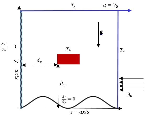
The treated problem is investigated inside a square cavity with length L filled with Cu-water nanofluid. The schematic diagram together with the rectangular Cartesian coordinate system is shown in Figure 1. The left and bottom walls are adiabatic whereas the top and right walls of the cavity are maintained with same cold temperature $T_c$. A rectangular heat source with temperature $T_h > T_c$ is positioned horizontally within the cavity. The top wall is assumed to move in the rightward direction with velocity $V_g$. In standard temperature the thermophysical properties of copper and water are given in Table 1. A uniform magnetic field B0 is applied along the negative x-axis direction normal to the vertical walls and acceleration of gravity g is acting in the downward direction. The nanofluid inside the cavity is considered as laminar, incompressible, and Newtonian. The equilibrium temperature is maintained for water and copper µ $$ u \frac {\partial u}{\partial x} + v \frac {\partial u}{\partial y} = - \frac {1}{\rho_ {n f}} \frac {\partial p}{\partial x} + \frac {\mu_ {n f}}{\rho_ {n f}} \left(\frac {\partial^ {2} u}{\partial x ^ {2}} + \frac {\partial^ {2} u}{\partial y ^ {2}}\right) $$ u u p u u u v x y x x y nf nf $$ \frac {\partial v}{\partial x} + v \frac {\partial v}{\partial y} = - \frac {1}{\rho_ {n f}} \frac {\partial p}{\partial y} + \frac {\mu_ {n f}}{\rho_ {n f}} \left(\frac {\partial^ {2} v}{\partial x ^ {2}} + \frac {\partial^ {2} v}{\partial y ^ {2}}\right) + \beta_ {n f} g \left(T - T _ {c}\right) - \frac {\sigma_ {n f}}{\rho_ {n f}} $$
2 2
2 2 0 2 1 nf nf nf c nf nf nf
v v p v v u v g T B v x y y T x y
$$ u \frac {\partial T}{\partial x} + v \frac {\partial T}{\partial y} = \frac {K _ {n f}}{\left(\rho C p\right) _ {n f}} \left(\frac {\partial^ {2} T}{\partial x ^ {2}} + \frac {\partial^ {2} T}{\partial y ^ {2}}\right) $$ ( ) nf The energy equation for heat source is $$ \left(\frac {\partial^ {2} T}{\partial x ^ {2}} + \frac {\partial^ {2} T}{\partial y ^ {2}}\right) = 0 $$
2 2 nanoparticles.
Based on the above assumptions, the conservation equations for steady two-dimensional MHD mixed convection flow are given in a dimensional form as following:
$$ \frac {\partial u}{\partial x} + \frac {\partial v}{\partial y} = 0 \tag {1} $$
The associated conditions of different walls and heat source are as following:
| Wall/Heat Source | Mathematical Expression | Flow Field | Thermal Field |
|---|---|---|---|
| Left wall | x=0,0≤ y≤ L | u =v=0 | ∂T =0 ∂x |
| Right wall | x= L,0≤ y≤ L | u =v=0 | T =T c |
| Top wall | y = L,0≤ x≤ L | u =V ,v=0 0 | T =T c |
| Wavy bottom wall | A y = [1 −cos2πλx] 2 | u =v=0 | ∂T =0 ∂y |
| Heat source surface | u =v=0 | T =T h | |
| Solid-fluid vertical interfaces of the heat source | ∂θ ∂θ = K s ∂X ∂X fluid solid | ||
| Solid-fluid horizontal interfaces of the heat source | ∂θ ∂θ = K s ∂Y ∂Y fluid solid | ||
| vNo-slip condition for all boundaries except the top wall |
Table 1: Boundary conditions in dimensional form.
The properties of nanofluid are given as following:
thermal expansion coefficient
$$ \left(\rho \beta\right) _ {n f} = \left(1 - \phi\right) \left(\rho \beta\right) _ {f} + \phi \left(\rho \beta\right) _ {s} \tag {8} $$ $$ \rho_ {n f} = \left(1 - \phi\right) \rho_ {f} + \phi \rho_ {s} \tag {6} $$ $$ \left(\rho C _ {p}\right) _ {n f} = \left(1 - \phi\right) \left(\rho C _ {p}\right) _ {f} + \phi \left(\rho C _ {p}\right) _ {s} \tag {7} $$ k nf nf p nf $$ \alpha_ {n f} = \frac {k _ {n f}}{\left(\rho C _ {p}\right) _ {n f}} \tag {9} $$ thermal diffusivity ( ) $$ \mu_ {n f} = \frac {\mu_ {f}}{\left(1 - \varphi\right) ^ {2}} $$ dynamic viscosity ( ) thermal conductivity ( ) ( ) ( ) ( ) To convert the governing equations (1) to (5) into nondimensional form the below mentioned nondimensional parameters are used
2 2 k k k k k
φ $$ - = \frac {\left(k _ {s} + 2 k _ {f}\right) - 2 \phi \left(k _ {f} - k\right)}{\left(k _ {s} + 2 k _ {f}\right) + \phi \left(k _ {f} - k\right)} $$ s f f s nf (11) k k k k k
2 φ $$ + 2 k _ {f}) + \phi \left(k _ {f} - k\right) $$
f s f f s
x y u v p X Y U V P L L V V V
, , $$ 1 = \frac {x}{L} Y = \frac {y}{L} U = \frac {u}{V} V = \frac {v}{V}, P = - $$
2 0 0 0 ρ nf
3 0 2 2 g TL T T V L Gr Gr R Ri T T
$$ 0 = \frac {T - T _ {c}}{T _ {h} - T _ {c}} G r = \frac {g \beta_ {f} \Delta T L ^ {3}}{\upsilon_ {f} ^ {2}} R e = \frac {V _ {0} L}{\upsilon_ {f}} R i = $$ β θ υ υ f c e Re (12) h c f f υ θ σ ρ υ α T T Ha B L T T $$ = \frac {T _ {s} - T _ {c}}{T _ {h} - T _ {c}} \Pr = \frac {\upsilon_ {f}}{\alpha_ {f}} H a = 1 $$ f s c s f f f h c f Pr /
0 Where V0 is the velocity of the top wall of the cavity and the nondimensional parameters Gr, Pr, Ri and Ha are the Grashof, Prandtl, Reynolds, Richardson, and Hartmann numbers respectively. Nondimensional form of the equations (1) to (5) are as following:
$$ \frac {\partial U}{\partial X} + \frac {\partial V}{\partial Y} = 0 $$
(13) µ $$ \frac {\partial U}{\partial X} + V \frac {\partial U}{\partial Y} = - \frac {\partial P}{\partial X} + \frac {\mu_ {n f}}{\rho_ {n f} v _ {f}} \frac {1}{R _ {e}} \left(\frac {\partial^ {2} U}{\partial X ^ {2}} + \frac {\partial^ {2} U}{\partial Y ^ {2}}\right) $$
2 2
2 2 1 nf U U P U U U V X Y X v R X Y
(14) nf f e $$ \frac {\partial V}{\partial X} + V \frac {\partial V}{\partial Y} = - \frac {\partial P}{\partial Y} + \frac {\mu_ {n f}}{\rho_ {n f} v _ {f}} \frac {1}{R _ {e}} \left(\frac {\partial^ {2} V}{\partial X ^ {2}} + \frac {\partial^ {2} V}{\partial Y ^ {2}}\right) + \frac {\beta_ {n f}}{\beta_ {f}} \frac {G r}{\mathrm {R e} ^ {2}} \theta - \frac {1}{R} $$
2 2 2
2 2 2 1 Re Re
V V P V V Gr Ha U V V X Y Y v R X Y
nf nf nf f e f
(15) $$ V \frac {\partial \theta}{\partial X} + V \frac {\partial \theta}{\partial Y} = \frac {\alpha_ {n f}}{\alpha_ {f}} \frac {1}{R _ {e} \Pr} \left(\frac {\partial^ {2} \theta}{\partial X ^ {2}} + \frac {\partial^ {2} \theta}{\partial Y ^ {2}}\right) $$
2 2
2 2 1 Pr
nf f e U V X Y R X Y
(16) The energy equation for the internal heat source $$ \left(\frac {\partial^ {2} \theta_ {s}}{\partial X ^ {2}} + \frac {\partial^ {2} \theta_ {s}}{\partial Y ^ {2}}\right) $$
2 2 (17) The nondimensional form of the associated conditions of heat source and boundaries of Table 2 are given as following:
| Wall/Heat Source | Mathematical Expression | Flow Field | Thermal Field |
|---|---|---|---|
| Left wall | X =0,0≤Y ≤ L | U =V =0 | ∂θ =0 ∂X |
| Right wall | X = L,0≤Y ≤ L | U =V =0 | θ=0 |
| Top wall | Y = L,0≤ X ≤ L | U =1,V =0 | θ=0 |
| Wavy bottom wall | A Y = [1 −cos2πλx] 2 | U =V =0 | ∂θ =0 ∂Y |
| Heat source surface | U =V =0 | θ=1 | |
| Solid-fluid vertical interfaces of the heat source | ∂θ ∂θ = K s ∂X ∂X fluid solid | ||
| Solid-fluid horizontal interfaces of the heat source | ∂θ ∂θ = K s ∂Y ∂Y fluid solid |
Table 2: Boundary conditions in dimensionless form.
$$ K = \frac {k _ {s}}{k _ {f}} $$
is the ratio of thermal conductivity of solid Where s f nanoparticle and base fluid. The local Nusselt number along the walls of the heat source is given as k Nu k N θ ∂ = − ∂ nf (19) f $$ \text {W h e r e} \frac {\partial \theta}{\partial N} \mathrm {i} $$ is the temperature gradient and N is the non-dimensional distances either X or Y directions acting normal to the surface. The average Nusselt number for the heat source is determined as
1 2 2 + + + + = + + + + ∫ ∫ ∫ ∫
D b D b D a D a
x x y y b t l r D D D D Nu Nu dX Nu dX Nu dY Nu dY a b x x y y (19)
The bulk average temperature is defined as
$$ s \theta_ {a v} = \int \frac {\theta}{\bar {V}} d \bar {V} $$ Where Dx and Dy are the dimensionless distances of the internal heat source from Y-axis and X-axis respectively, a and b are the height and width of the heat source, is the volume of the cavity.
b. Numerical Procedure The governing equations have been simulated using finite element technique of Galerkin’s method. Finite element method is useful to solve the problems with complicated geometries where analytical solutions cannot be obtained. It divides up a very complicated problem into small elements that can be solved in relation to each other. This method has become an integral part of the design and development of numerous engineering systems.
In this simulation process, the whole domain has been subdivided into definite number of triangular meshes. After that the conservation equations (13-17) accompanying boundary conditions Table 3 are converted into a system of integral equations with the help of Galerkin’s method. By using Newton-Raphson approach these equations in nonlinear form are converted into linear form and then triangular factorization process is used for solving these linear algebraic equations to find the values of velocity components (U,V) pressure (P) and temperature (θ). The convergence technique for the solution benchmark is demarcated as 1 6 10 m m ψ ψ + − − < with, m as the iteration number and Ψ as Ψ(U,V,θ). Figure 2 expresses the generated mesh of the computational domain for simulation. It consists of 25,929 domain elements and 829 boundary elements.
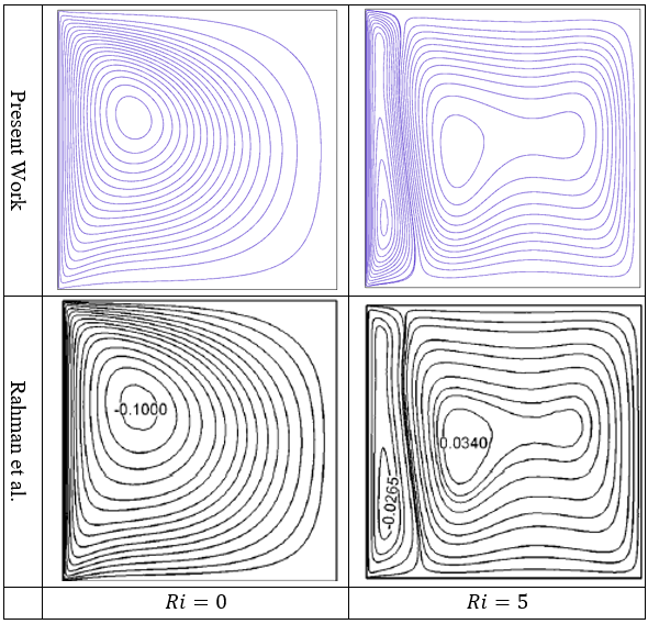
c. Code Verification To verify the present solution procedure, it has been compared against the study of MHD combined convection of nanofluid in a moving lid cavity of Rashad, et al. [5]. The comparison for various Hartmann numbers at Ri=1 and φ=0.05 has been demonstrated in Figures 3 & 4. These figures are almost concurrent and this justification boosts up the assurance in the graphical and numerical results of the current work.
![Figure 3: Comparison of streamlines between present study and Rahman, et al. [26] at φ=0.04.](/fulltextimages/10923/fig_3.png)
![Figure 4: Comparison of isotherms between present study and Rahman, et al. [26] at φ=0.04.](/fulltextimages/10923/fig_4.png)
| Water | Copper (Cu) | |
|---|---|---|
| C_(p ) (J/kgK) | 4179 | 385 |
| ρ (kg/m^3) | 997.1 | 8933 |
| μ(kg/ms) | 9.09×10^-4 | - |
| k(W/mK) | 0.613 | 401 |
| β(K^-1) | 21×10^-5 | 1.67×10^-5 |
| σ(Sm^-1) | 0.05 | 5.96×10^-7 |
Table 3: Thermophysical properties of base fluid and solid nanoparticles
Results and Discussion
The numerical results of the current study are presented graphically through stream function contours (streamline), dimensionless temperature contours (isotherms), and average Nusselt number. The considered nondimensional parameters those have a direct impact on fluid flow and heat transfer inside the cavity are as follows: Hartmann number (0≤Ha≤90), wave number of wavy surface (0≤λ≤4), and the ratio of heat source height and cavity height 1 1 20 3 a L < < .
Reynolds number Re, Prandtl number Pr and width of heat source are considered constant a Re=100, Pr=6.13 and b=L/4s s. Dx and Dy are also kept constant as Dx=Dy=0.4. The whole investigation is conducted in the mixed convection region taking Cu-water nanofluid as functional fluid within the cavity and the range of volume fraction of nanoparticle is considered as (0≤∅≤0.09). The flow characteristics and thermal distribution inside the cavity are investigated through streamlines and isothermal lines whereas the heat transfer rate is analyzed through average Nusselt number.
d. Effect of Nanoparticle and Wave Number of Wavy
Surface
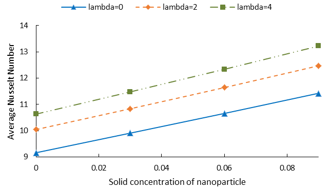
Figure 5 demonstrates the variation of average Nusselt
number as a function of wave number of wavy surface and
solid concentration of nanoparticles at
$$ H a = 0, \frac {a}{L} = \frac {1}{1 0} \mathrm {i n t h e} $$ mixed convection region. As seen from figure, heat transfer rate increases with the increasing value of wave number as well as the volume fraction of nanoparticles. Generally, by increasing the number of undulation of wavy surface λ, the fluid within the cavity moves up and down and generates some heat due to the friction between the wall and the nanofluid which escalates the fluid flow and heat transfer rate. It is clearly evident from figure that, heat transfer rate increases with the augmentation of number of undulations of wavy surface. From figure it is also evident that, heat transfer rate increases with the increasing value of solid concentration of nanoparticles. The reason is that, with the presence and increasing value of copper nanoparticles, the thermal conductivity of the mixture (nanofluid) increases automatically since the k of copper≫k of water which results in conducting more heat and consequently increases the heat transfer rate. Analyzed data of Figure 5 reveals that, with the increasing value of λ from 0 to 2 and 4, heat transfer rate increases about 10% and 16% for pure base fluid and about 9% and 16% for nanofluid with 6% of copper nanoparticles.
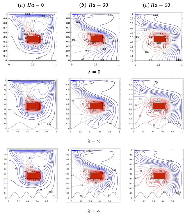
e. Effect of Hartmann Number and Wave Number of Wavy Surface Figure 6 exhibits the effects of Hartmann number (Ha) and wave number of wavy surface λ on fluid flow and heat transfer through streamlines at φ=0.04 in the mixed convection region. To divulge the consequence of λ and Ha exclusively other influencing factors namely Richardson number and volume fraction of nanoparticle are kept constant as Ri=1 and φ=0.04. In the mixed convection region, both the shear force generated by the top moving wall and buoyancy force generated due to the temperature gradient of the heat source and cold walls are equally dominant. At (Ha=0) the forced convection due to the shear force creates a primary clockwise rotating unicellular vortex along its direction and the buoyancy force prompts this circulation to flow around the heat source almost symmetrically which is clearly evident in Figure 6a. By instigation of magnetic field Ha=30, a Lorentz force is created perpendicularly to the direction of applied magnetic field. The main characteristics of Lorentz force is suppressing the buoyancy force and decreasing the heat flux which is clearly evident in Figure 6b. With further increase of Hartmann number (Ha=60), the effect of buoyancy almost diminishes and only the forced convection due to the moving lid becomes dominant. The flow strength is weakened due to the strong magnetic field and as Figure 6c the streamlines are squeezed towards the moving wall. With the instigation and increasing the number of undulation of wavy surface λ, no major change is noticed in the pattern of streamlines except the intensity of the streamlines increases and the streamlines near the sinusoidal bottom wall take the shape of this wall.
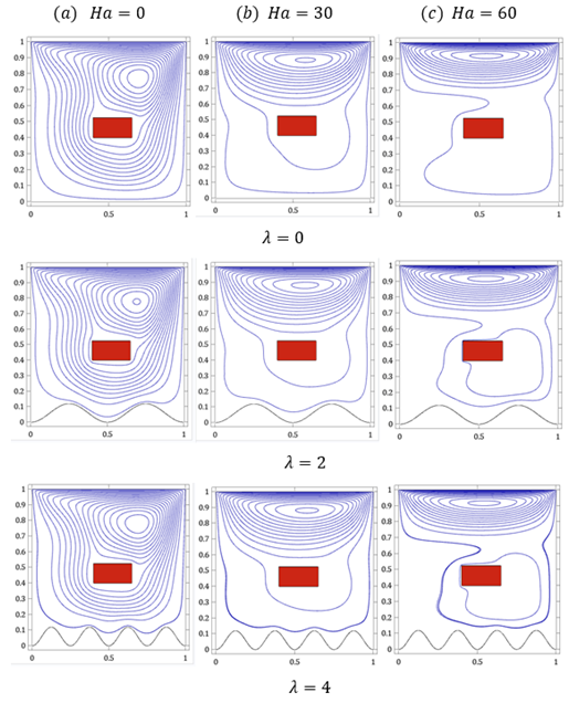
Figure 7 exhibits the effects of Hartmann number Ha and wave number of wavy surface λ on temperature field through the isothermal lines at φ=0.04. As seen from figure, in absence of magnetic field the isothermal lines show the typical convective twist within the cavity. The lines are more distorted creating a plume in the left upper part of the heat source due to high convective current inside the cavity. With the increasing value of Hartmann number at Ha=30, the distortion of isothermal lines started to disappear and further increase of this number to Ha=60shows the minimum nonlinearity of isothermal lines and the plume above the heat source vanishes gradually showing the conduction mode of heat transfer. Also near the heat source the space between the isothermal lines is comparatively much which is a clear indication of low heat transfer coefficient in the heat source wall.
$$ R i = 1, \frac {a}{L} = \frac {1}{8} $$
| Ha=0 | Ha=30 | Ha=60 | Ha=90 | |
|---|---|---|---|---|
| λ=0 | 10.9972 | 8.04336 | 5.08925 | 4.63684 |
| λ=1 | 12.213 | 8.2724 | 5.02153 | 4.56101 |
| λ=2 | 11.7897 | 8.18533 | 4.967 | 4.5059 |
| λ=3 | 12.0394 | 8.22349 | 4.96059 | 4.49843 |
| λ=4 | 12.1303 | 8.23649 | 4.95227 | 4.48933 |
Table 4: f.
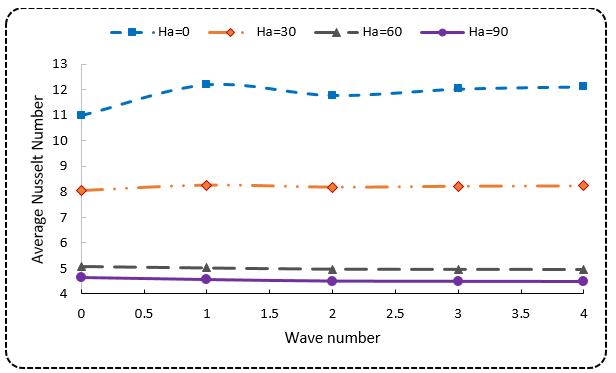
The rate of heat transfer in terms of average Nusselt number as a function of Hartmann number and wave number of wavy surface is depicted in Figure 8 through a numerical graph. By increasing the number of undulation of wavy surface λ, some heat is generated due to the friction force as described in Figure 5 and intensifies the fluid flow. It has a clear effect at Ha=0 in Figure 8. But with the increasing value of Ha, Lorentz force balances both the buoyancy force and friction force. Fig. 8 clearly exposes that with the increasing value of λ, average Nusselt number increases gradually at Ha=0, it increases very slightly at Ha=30 but at Ha=60 and 90, average Nusselt number started to decrease very slightly. Figure also depicts that, the rate of heat transfer decreases with the increasing value of Hartmann number irrespective of wave number. Analyzed data of Figure 8 reveals that, with the increasing value of Ha from 0 to 30, heat transfer rate decreases about 27% at λ=0 and about 32% at λ=4. On the other hand, with the augmentation of wave number from 0 to 4 heat transfer rate increases about 10% at Ha=0 but it decreases about 3% at Ha=60.For more clarification data is given in Table 4.
f.
Effect of the Ratio of Heat Source Height and Cavity
Height
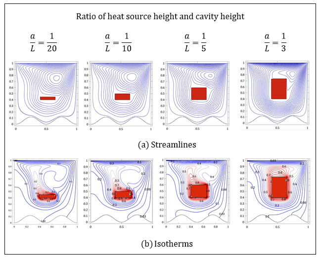
Figure 9a depicts the effect of the ratio of heat source
height and cavity height on flow behaviour inside the cavity
through streamlines at φ=0.04 in the mixed convection
region and in absence of magnetic field. Figure shows that, at
$$ \frac {a}{L} = \frac {1}{2 0}, $$
, the streamlines are characterized by a primary clockwise unicellular vortex keeping the center in the upper right corner of the cavity which is produced due to the combined effect of forced convection and buoyancy convection. As seen from figure, with the increasing value of the ratio of heat source height and cavity height, the
streamlines are squeezed towards the upper right corner
due to the space constraint inside the cavity. Figure 9 (b)
depicts the corresponding effect of the ratio of heat source
height and cavity height on the temperature field inside the
cavity. Figure shows that, at
$$ \frac {a}{L} = \frac {1}{2 0} $$
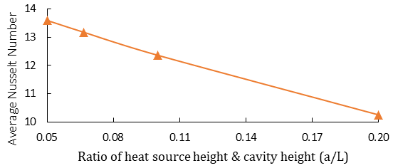
, the isothermal lines are distributed within the whole cavity creating a plume above the heat source. As seen from figure, with the increasing value of the ratio, the isothermal lines are gradually gathering around the heat source which is a clear indication of conduction dominant heat transfer. Figure 10 demonstrates the variation of average Nusselt number for different values of heat source height and cavity height ratio (a/L) at Ri=1, φ=0.04 and Ha=0. From figure it is obvious that, average Nusselt number decreases with the increasing value of heat source height & cavity height ratio. Since the cavity height and heat source width are constant in this case so in other words it can be said that average Nusselt number decreases with the increasing value of heat source height. It is very logical because heat diffusion as well as nanofluid temperature will be increased with the increasing value of heat source height or area of heat source surface. It will reduce the temperature gradient between the heat source and cold wall of the cavity which in turn reduce the heat transfer rate. The analyzed data of Figure 10 exposes that in absence of magnetic field and in the mixed convection region, with the increasing ratio of heat source height and cavity height from 1 20 and then 1 5 to 1 10 heat transfer rate decreases about 9% and 25% respectively in nanofluid with 4% of nanoparticle.
g. Variation of Heat Transfer Rate at Different Walls of Heat Source
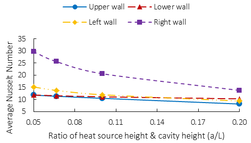
| Upper wall | Lower wall | Left wall | Right wall | Total | |
|---|---|---|---|---|---|
| 0.1 | 11.81 | 11.85 | 15.16 | 29.675 | 13.595 |
| 0.1 | 11.332 | 11.552 | 13.747 | 25.595 | 13.174 |
| 0.1 | 10.482 | 11.102 | 11.959 | 20.626 | 12.364 |
| 0.2 | 8.1396 | 10.278 | 9.3662 | 13.748 | 10.253 |
| 0.3 | 4.2261 | 9.5337 | 7.6616 | 9.3568 | 5.4695 |
Table 5: Numerical values of Nuavg at different walls of heat source for different values of a/L at Ri=1, φ=0.04 and Ha=0.
Figure 11 shows the variation of average nusselt number at different walls of the heat source for different values of a L at φ=0.04. From figure it is clearly evident that, average Nu
decreases with the increasing value of this ratio. Table 5
shows that maximum average Nu is 29.67 which occurs at
the right wall for the ratio
$$ \frac {a}{L} = \frac {1}{2 0} $$
and minimum average Nu is 4.2261 which occurs at the upper wall for the ratio
$$ \frac {a}{L} = \frac {1}{3}. $$
Conclusion
With the increasing value of Ha from 0 to 30, heat transfer rate decreases about 27% at λ=0 and about 32% at λ=4.On the other hand, with the augmentation of wave number from 0 to 4 heat transfer rate increases about 10% at Ha=0but it decreases about 3% at Ha=60.
In absence of magnetic field, with the increasing value of λ fom 0 to 2 and 4, heat transfer rate increases about 10% and 16% for pure base fluid and about 9% and 16% for nanofluid with 6% of solid nanoparticles.
In absence of magnetic field and in the mixed convection region, with the increasing ratio of heat source height and cavity height from
1 20 to 1 10 and 1 5 heat transfer rate decreases about 9% and 25% respectively in nanofluid with 4% nanoparticle.
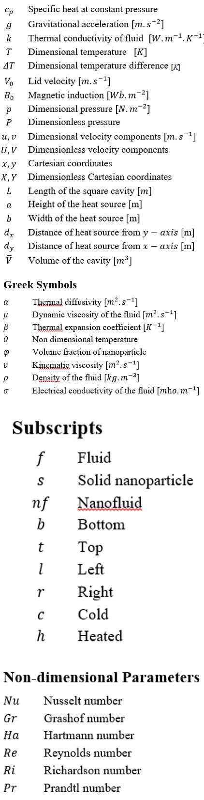
Nomenclature
References
-
Abu Nada E, Chamkha AJ (2010) Mixed convection flow in a lid-driven inclined square enclosure filled with a nanofluid. European Journal of Mechanics B/Fluids 29(6): 472-482.
-
Ahmadi MH, Mirlohi A, Nazari MA, Ghasempour R (2018) A review of thermal conductivity of various nanofluids. Journal of Molecular Liquids 265: 181-188.
-
Alim MA, Kabir KH, Andallah LS (2016) MHD natural convection flow along a vertical, wavy surface with heat generation and pressure work. AIP conference proceedings 1754(1): 050032.
-
Alsabery AI, Kadhim HT, Ismael MA, Hashim I, Chamkha AJ (2021) Impacts of amplitude and heat source on natural convection of hybrid nanofluids into a wavy enclosure via heatline approach. Waves in random and complex media 31(4): 1060-1084.
-
Armaghani T, Sadeghi MS, Rashad AM, Mansour MA, Chamkha AJ, et al. (2021) MHD mixed convection of localized heat source/sink in an Al2O3-Cu/water hybrid nanofluid in L-shaped cavity. Alexandria Engineering Journal 60(3): 2947-2962.
-
Basak T, Roy S, Sharma PK, Pop I (2009) Analysis of mixed convection flows within a square cavity with linearly heated side wall(s). International Journal of Heat and Mass Transfer 52(9-10): 2224-2242.
-
Basak T, Roy S, Singh SK, Pop I (2010) Analysis of mixed convection in a lid-driven porous square cavity with linearly heated side walls. Int J Heat Mass Transfer 53: 1819-1840.
-
Billah MM, Rahman MM, Sharif UM, Rahim NA, Saidur R, et al. (2011) Numerical analysis of fluid flow due to mixed convection in a lid driven cavity having a heated circular hollow cylinder. International Communications in Heat and Mass Transfer 38(8): 1093-1103.
-
Boulahia Z, Wakif A, Sehaqui R (2016) Numerical investigation of mixed convection heat transfer of nanofluid in a lid driven square cavity with three triangular heating blocks. International Journal of Computer Applications 143(6): 37-45.
-
Chamkha AJ, Abu Nada E (2012) Mixed convection flow in single- and double-lid driven square cavities filled with water- Al2O3 nanofluid: Effect of viscosity models. European Journal of Mechanics B/Fluids 36: 82-96.
-
Chowdhury K, Alim A (2019) MHD mixed convection flow in a lid driven enclosure with a sinusoidal wavy wall and a heated circular body. International Journal of Fluid echanics & Thermal Sciences 5(4): 102-110.
-
Chowdhury K, Alim A, Hossen M (2020) Natural convection in a partially heated and cooled square enclosure containing a diamond shaped heated block. International Journal of Fluid Mechanics & Thermal Sciences 6(1): 1-8.
-
Chowdhury K, Alim MdA (2023) Mixed convection in a double lid-driven wavy shaped cavity filled with nanofluid subject to magnetic field and internal heat source. Journal of Applied Mathematics 2023.
-
Dayf A, Feddaoui M, Bouchta S, Charef A, Ihssini HE (2021) Effect of nanoparticles and base fluid types on natural convection in a three dimensional cubic enclosure. Mathematical Problems in Engineering 2021: 1-13.
-
Dehghani MS, Toghraie D, Mehmandoust B (2019) Mixed convection nanofluid flow through a grooved channel with internal heat generating solid cylinders in the presence of an applied magnetic field. Heat Transfer Research 50(3): 287-309.
-
Ghaneifar M, Raisi A, Ali HM, Talebizadehsardari P (2020) Mixed convection heat transfer of 𝐴𝑙2𝑂3 nanofluid in a horizontal channel subjected with two heat sources. Journal of Thermal Analysis and Calorimetry 143: 2761- 2774.
-
Hossain MS, Alim MA (2014) MHD free convection within trapezoidal cavity with non-uniformly heated bottom wall. International Journal of Heat and Mass Transfer 69: 327-336.
-
Hussein AK, Hamzah HK, Ali FH, Kolisi I (2020) Mixed convection in a trapezoidal enclosure filled with two layers of nanofluid and porous media with a rotating circular cylinder. Journal of Thermal Analysis and Calorimetry 141: 2061-2079.
-
Kakac S, Pramuanjaroenkij A (2009) Review of convective heat transfer enhancement with nanofluids. International Journal of Heat and mass Transfer 52(13- 14): 3187-3196.
-
Kalteh M, Javaherdeh K, Azarbarzin T (2014) Numerical solution of nanofluid mixed convection heat transfer in a lid-driven square cavity with a triangular heat source. Powder Technology 253: 780-788.
-
Kareem AK, Mohammed HA, Hussein AK, Gao S (2016) Numerical investigation of mixed convection heat transfer of nanofluids in a lid-driven trapezoidal cavity. International communications in Heat and Mass Transfer 77: 195-205.
-
Kasaeipoor A, Ghasemi B, Aminossadati SM (2015) Convection of Cu-water nanofluid in a vented T-shaped cavity in the presence of magnetic field. International Journal of thermal sciences 94: 50-60.
-
Khan AQ, Rasheed A (2019) Mixed convection magnetohydrodynamics flow of a nanofluid with heat transfer: A numerical study. Mathematical Problems in Engineering 2019: 1-14.
-
Keya ST, Yeasmin S, Rahman MM, Karim MF, Amin MR (2022) Mixed convective heat transfer in a lid- driven enclosure with a double-pipe heat exchanger. International Journal of thermofluids 13: 100131.
-
Mahalakshmi T, Nithyadevi N, Oztop HF, Abu Hamdeh N (2018) MHD mixed convective heat transfer in a lid- driven enclosure filled with Ag-water nanofluid with center heater. International Journal of Mechanical Sciences 142: 407-419.
-
Rahman MM, Billah MM, Hasanuzzaman M, Saidur R, Rahim NA (2012) Heat transfer enhancement of nanofluids in a lid driven square enclosure. Numerical Heat Transfer 62(12): 973-991.
- Solution-Processed Chiral Perovskites for Biomedical Applications
- Nanotechnology in Health Chemistry and Medicine: Current Challenges and Future Directions
- Human Exposure to Micro- and Nanoplastics: Pathways, Toxicity, and Intervention Strategies
- Exosome Nanomedicine for Cancer Therapy
- Micro and Nanoplastics–Plastisphere, Biotoxicity, Impact on Human Health, and Mitigation Strategies
- Process Validation of Cefixime Powder for Suspension Dosage Form, 50 mL