Tailored Synergy: Synthesis and In-Depth Structural Analysis of x[Ni0.2Cu0.3Co0.5Fe2O4] + (1-x)[Ba0.7Sr0.3TiO3] Composites
M E Composites with composition x[Ni0.2 Cu0.3 CO0.5 Fe2O4] + (1-x)[Ba0.7Sr0.3TiO3], Where x varying from 0.1 to 0.4 in molar ratio, were prepared by standard double sintering ceramic technique. The presence of ferrites phase, namely [Ni0.2 Cu0.3 CO0.5 Fe2O4] and ferroelectric phase, namely [Ba0.7Sr0.3TiO3], were confirmed by X-Ray Diffraction analysis, whereas SEM micrographs were obtained to study the morphology of samples. The x ray diffraction patterns exhibit a set of well-defined ferrites and ferroelectric peaks. The tetragonality ratio c/a, of the ferroelectric phase remains the same in all the samples, the porosity varies from 20% to30% while the average grain diameter lies in the range of 0.5μm to 2 μm.
Introduction
Ferroelectrics and ferrites play crucial roles in various electronic applications, from nonvolatile materials to data storage. In the pursuit of advancing materials science, the exploration of multifunctional composites has gained significant attention. These composites, which combine different phases, offer a wide range of applications, from electronic devices to energy storage systems [1, 2, 3, 4]. One promising avenue is the synthesis and characterization of ferrite-ferroelectric composites, leveraging the unique properties of both materials. Ferrite-ferroelectric composites combine magnetic ferrites, typically composed of iron oxide compounds, with ferroelectrics, which exhibit spontaneous electric polarization. This combination results in materials with enhanced electromagnetic and ferroelectric properties [5, 6, 7, 8, 9]. Key aspects of these composites include synthesis, electromagnetic and ferroelectric properties, magnetoelectric coupling, tunable microwave devices, energy harvesting, and lead-free ferroelectrics [10, 11, 12, 13, 14, 15, 16, 17].
There are two types of multiferroics: single-phase, where one material possesses both ferroelectric and magnetic ordering, and composites, consisting of different phases with ferroelectric and magnetic properties [18, 19, 20, 21]. Examples include BiFeO3 and BiMnO3 for single-phase, and (Ni,Zn)Fe2O4−BaTiO3, BaSrTiO3−(Ni,Zn)Fe2O4, Ni(Co,Mn) Fe2O4−BaTiO3, and CoFe2O4−BaTiO3 for composites [22, 23, 24, 25].
In this research, the focus is on integrating Ni-Cu-Co Ferrite with BST, aiming to exploit synergies from their complementary properties. Various compositions are explored to find the optimal blend with superior attributes for specific applications. The study involves synthesizing the x[Ni0.2Cu0.3CO0.5Fe2O4] + (1-x) [Ba0.7Sr0.3TiO3] composites through the solid-state method, followed by in-depth characterization of their structural properties. Ultimately, the goal is to contribute valuable insights for the development of advanced materials with tailored functionalities and improved performance.
Experiment
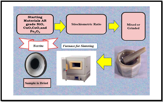
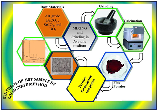
Both ferrite and ferroelectric phases were prepared through a standard solid state reaction method, using AR grade NiO, CuO, CoO and Fe2O3 powders in molar ratio as starting materials (Ferrite). Whereas ferroelectric phases was prepared by same method, using AR grade BaCO3, 3SrCO3, and TiO2 as starting materials. The mixture was pre- sintered at 800ºC for 10 hours in each case. ME Composites were synthesized by mixing 10 to 40 molar percentage of ferrite phase with 90 to 60 mole percentage of ferroelectric phase respectively. And presintered at 1000℃ for 12 hours. These composites were pressed in to pellets about 1 gram, 2mm in thickness and 1cm in diameter and subjected to final sintering at 1200 ºC for about 15 hours in muffle furnace and then furnace cooled. A detailed Schematic synthesis method for ferrite and ferroelectric phase is shown in Figures 1 & 2.
Characterization
The presence of crystalline phases and crystal structure of the composites and constituents phases were determined by powder X-Ray Diffraction, using Cu-Kα monochromatic radiation of wavelength 1.5148Å, in a wide range of glancing angle 2θ from 10º to 90º the micrographs of the samples were obtained to study the surface morphology, grain size and microstructure through SEM.
Results and Discussion
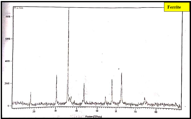
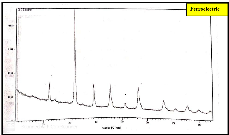
X-Ray diffraction patterns of the Ni0.2Cu0.3CO0.5Fe2O4 represented from the Figure 3. X ray diffraction patterns indexing by JCPD data ferrite and ferroelectric exhibits face centered cubic structure and tetragonal structure. The absence of extra line confirms the formation of single phase ferrites the calculated values of interplanar distances and lattice constant are in good agreement with those expected for spinel ferrites. The cyclic sum of miller indices is even number which confirms FCC Structure (Table 1). The same behaviour is observed in the present case. X ray diffraction pattern of Ba0.7Sr0.3TiO3 ferroelectric phase (Figure 4) are indexed with the help of JCPD data. The observed doublet (002) (200); (103) (301); and (113) (311) without additional peaks confirms the formation of tetragonal perovskite structure of ferroelectric phase (Table 2).
| 2Θ | Θ | sin Θ | hkl | d (Å) obs | D (Å) cal | Lattice Constant |
|---|---|---|---|---|---|---|
| 18.4454 | 9.2227 | 0.1602 | 111 | 4.8101 | 4.8146 | a=8.3389Å |
| 30.308 | 15.154 | 0.2614 | 220 | 2.9491 | 2.9482 | |
| 35.7138 | 17.8569 | 0.3066 | 311 | 2.5141 | 2.5142 | |
| 37.1497 | 18.5748 | 0.3 185 | 222 | 2.4202 | 2.4072 | |
| 43.3115 | 2,16,557 | 0.369 | 400 | 2.089 | 2.0847 | |
| 53.9054 | 26.9527 | 0.4532 | 422 | 1.7008 | 1.7021 | |
| 5,74,299 | 28.7149 | 0.4804 | 511 | 1.6046 | 1.6048 | |
| 74.598 | 37.299 | 0.6059 | 622 | 1.2722 | 1.2571 |
Table 1: Lattice constant of Ferrite sample.
| 2Θ | Θ | SinΘ | hkl | d (Å) cal | d (Å) obs | Lattice Parameter |
|---|---|---|---|---|---|---|
| 22.243 | 1 1 .1213 | 0.1929 | 1 | 3.9966 | 39,968 | a=3.99463Å c=3.9986Å (Tetragonality) c/a=1.001 |
| 31.678 | 15.8389 | 0.2729 | 110 | 2.8244 | 2.8246 | |
| 39.035 | 19.5177 | 0.3341 | 111 | 2.3074 | 2.3075 | |
| 45.487 | 22.7436 | 0.3866 | 200 | 1.994 | 1.9941 | |
| 51.184 | 25.5921 | 0.432 | 210 | 1.7846 | 1.784 | |
| 57.574 | 28.7872 | 0.4815 | 211 | 16,008 | 1.6009 | |
| 66.187 | 33.0935 | 0.546 | 210 | 1.41 1 8 | 1 .4119 | |
| 70.707 | 35.3535 | 0.5786 | 103 | 1 .3323 | 1 .3323 | |
| 75.339 | 37.6694 | 0.6111 | 301 | 1.0261 | 1.2615 | |
| 79.623 | 39.8116 | 0.6402 | 222 | 1.204 | 1.204 | |
| 83.834 | 41.9168 | 0.668 | 320 | 1.1539 | 1.153 |
Table 2: Lattice constant of Ferroelectric sample.
The absence of intermediate peaks apart from x[Ni0.2 Cu0.3 CO0.5 Fe2O4] + (1-x) [Ba0.7Sr0.3TiO3] ferrites and ferroelectric phases Figure 5 is attributed to the fact that no chemical reaction have been taken between the constituent phases during final sintering. The peaks exhibit both perovskite (110) and cubic (311) peaks which are the characteristics of ferroelectric and ferrites phase respectively. The lattice parameters in case of composites (Tables 3-6) are almost equal to those of constituents phases. This indicates the absence of structural changes with varyingmolar portions [26, 27]. However the intensity of peaks is found decrease with components. This is due to the capacity of ferrites phase to dissolve in to the spinel lattice [26, 27].The data on patterns is given in tables from 1 to 6. Figures 1&2 exhibit a set of well defined ferric and ferroelectric peaks [26, 27]. The variation of X ray Density , actual density and porosity with doping is shown in Figure 6.
![Figure 5: XRD patterns of x[Ni0.2 Cu0.3 CO0.5 Fe2O4] + (1-x)[Ba0.7Sr0.3TiO3] ( x=0.1,0.2,0.3 and 0.4).](/fulltextimages/12044/fig_5.png)
| 2Θ | Θ | SinΘ | hkl | d cal | Lattice Parameter |
|---|---|---|---|---|---|
| 22.156 | 11.078 | 0.1922 | *( 100) | 4.0111 | Ferrite phase a=8.3758Å |
| 30.146 | 15.073 | 0.26 | 220 | 2.965 | |
| 31.574 | 15.787 | 0.2721 | *(101) | 2.8331 | Ferroelectric phase a=8.3758Å c=4.0096Å |
| 35.535 | 17.7675 | 0.3052 | 311 | 2.5259 | |
| 38.901 | 19.4505 | 0.3329 | *(111) | 2.3157 | (tetragonality) c/a=1.0009 |
| 42.624 | 21.312 | 0.3634 | 400 | 2.1214 | |
| 45.242 | 22.621 | 0.3846 | *(002) | 2.004 | |
| 50.971 | 25.4855 | 0.43028 | * (210) | 1.7916 | |
| 53.572 | 26.786 | 0.4507 | 422 | 1.7105 | |
| 56.241 | 28.1205 | 0.4713 | *(211) | 1 .6357 | |
| 62.735 | 31.3675 | 0.5205 | 440 | 1.4811 | |
| 65.965 | 32.9825 | 0.5444 | *(220) | 1.4161 | |
| 70.589 | 35.2945 | 0.5778 | * (221) | 1.3342 | |
| 75.077 | 37.5385 | 0.6093 | *( 301) | 1.2652 | |
| 79.395 | 39.6975 | 0.6387 | *(311) | 1.2069 | |
| 83.713 | 41.8565 | 0.6673 | *(222) | 1.1553 | |
| 92.366 | 46.183 | 0.7216 | 731 | 1.0683 | |
| 22.326 | 11.163 | 0.194 | * (100) | 3.982 | Ferrite phase a=8.3638Å |
| 30.23 1 | 15.116 | 0.261 | *(220) | 2.956 | |
| 45.616 | 22.808 | 0.388 | * ( 002) | 1.989 | Ferroelectric phase a=8.39796Å c=3.9809Å |
| 51.362 | 25.681 | 0.433 | * (210) | 1.779 | |
| 56.717 | 28.359 | 0.475 | * (211) | 1.623 | |
| 62.888 | 31.444 | 0.522 | 440 | 1.478 | |
| 66.05 | 33.025 | 0.545 | * (220) | 1.415 | (tetragonality) c/a=1.0003 |
| 71.099 | 35.55 | 0.581 | * (221) | 1.326 | |
| 75.638 | 37.819 | 0.613 | * (301) | 1.257 | |
| 79.412 | 39.706 | 0.639 | * (311) | 1.207 | |
| 84.376 | 42.188 | 0.672 | * (222) | 1.148 | |
| 93.063 | 46.532 | 0.726 | *(731) | 1.062 |
Table 3: Lattice parameter of 0.1[Ni0.2 Cu0.3 CO0.5 Fe2O4] + 0.9 [Ba0.7Sr0.3TiO3].
| 2Θ | Θ | SinΘ | hkl | d cal | Lattice Parameter |
|---|---|---|---|---|---|
| 22.14 | 11.07 | 0.192 | * (100) | 4.0172 | Ferrite phase a=8.3747Å |
| 30.18 | 15.09 | 0.26 | * (220) | 2.9616 | |
| 31.54 | 15.77 | 0.272 | *(106 ) | 2.8363 | Ferroelectric phase a=4.0103Å c=4.0128Å |
| 35.55 | 17.776 | 0,3053 | * (311) | 2.5251 | |
| 38.9 | 19.451 | 0.333 | *(111) | 2.3157 | |
| 43.22 | 21.61 | 0.368 | * (400) | 2.0931 | |
| 45.31 | 22.665 | 0.385 | * (002) | 2.0013 | (tetragonality) c/a=1.0006 |
| 50.94 | 25.469 | 0.43 | *(210) | 1.7928 | |
| 53.64 | 26.82 | 0.451 | *(422) | 1.7086 | |
| 56.22 | 28.1 12 | 0.471 | *(211) | 1.636 | |
| 62.8 | 31.402 | 0.521 | *(440) | 1.4797 | |
| 66.02 | 33.008 | 0.545 | *(220) | 1 .4150 | |
| 70.5 | 35.252 | 0.577 | *(221) | 1.3356 | |
| 75.3 | 37.649 | 0.611 | *(301) | 1.2621 | |
| 79.57 | 39.783 | 0.64 | *(31 1) | 1.2047 | |
| 83.7 | 41.848 | 0.667 | *(222) | 1.1557 | |
| 92.2 | 46.098 | 0.721 | *(731) | 1.0699 | |
| 2Θ | Θ | SinΘ | hkl | d cal | Lattice parameter |
| 22.19 | 11.095 | 0.192 | *(100) | 4.007 | Ferrite phase a=8.3775Å |
| 30.16 | 15.082 | 0.26 | *(200) | 2.963 | |
| 31.57 | 15.787 | 0.272 | * (111) | 2.833 | Ferroelectric phase a=4.007Å c=4.009Å |
| 35.54 | 17.768 | 0.305 | *(311) | 2.526 | |
| 38.94 | 19.468 | 0.333 | *(111) | 2.313 | |
| 43.2 | 21.601 | 0.368 | *(400) | 2.094 | (tetragonality) c/a=1.0005 |
| 45.26 | 22.629 | 0.385 | * (002) | 2.003 | |
| 51.01 | 25.503 | 0.431 | * (210) | 1.79 | |
| 53.62 | 26.812 | 0.451 | *(422) | 1.709 | |
| 56.26 | 28.129 | 0.472 | *(211) | 1.635 | |
| 62.82 | 31.41 | 0.521 | *(440) | 1.479 | |
| 65.9 | 32.949 | 0.544 | *(220) | 1.417 | |
| 75.26 | 37.632 | 0.611 | * (301) | 1.263 | |
| 79.24 | 39.621 | 0.638 | * (311) | 1.209 | |
| 92.4 | 46.2 | 0.722 | *(731) | 1.068 |
Table 4: Lattice parameter of 0.3[Ni0.2 Cu0.3 CO0.5 Fe2O4] + 0.7 [Ba0.7Sr0.3TiO3].
![Figure 6: X-ray Density and Porosity of x[Ni0.2Cu0.3Co0.5Fe2O4] + (1-x)[Ba0.7Sr0.3TiO3] Composites.](/fulltextimages/12044/fig_6.png)
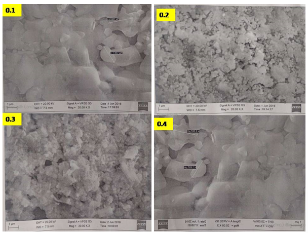
SEM analysis
Scanning Electron Microscopy (SEM) is a powerful imaging technique that provides high-resolution, three- dimensional images of the surface morphology of ferrites & ferroelectric samples. The average grain size was estimated by Cotrell’s method [28], which lies in between 0.8 µm to 2.0 µm and decrease with increase in mole percentage of ferrites phase (Figure 7) and cause for the decrease of mean free path of electrons. The porosity is an inherent phase associated with the samples prepared by ceramic method. Porosity is a crucial aspect of materials prepared by ceramic methods, and it plays a significant role in influencing the properties and applications of these materials In the present case porosity in composites varies from 20 to 30 percent (Figure 6). The grain growth in the ME composite is assigned to the presence of inclusions and pores in the solid solution which migrate to the grain boundary. The grain growth in the ME Composite depends on the particle size of individual phases and their distribution , homogeneity of chemical composition and sintering conditions [26, 27, 28]. Increase in ferrite phase decrease the porosity and hence decrease the grain size. This leads to decrease in magnetization of the ME composites.
Because, of large grain and less effective in inducing ferrite and ferroelectric coefficients rather than smaller ones [26, 27, 28].
Conclusions
A simple and cost-effective solid-state technique was employed to synthesize both ferrite & ferroelectric samples. Phase of Ferrite sample cubic, Ferroelectric as tetragonal and further composites were analyzed through XRD analysis. The study focused on investigating variation of structural properties of x[Ni0.2Cu0.3Co0.5Fe2O4] + (1-x)[Ba0.7Sr0.3TiO3] Composites. The presence of cubic phase of [Ni0.2Cu0.3CO0.5 Fe2O4], ferroelectric phase (tetragonal) [Ba0.7Sr0.3TiO3], were confirmed by X-Ray Diffraction analysis and SEMaverage grain diameter lies in the range of 0.5µm to 2 µm.
References
-
Smith A (2021) Key Electromagnetic and Ferroelectric Properties of Ferrite-Ferroelectric Composites. Journal of Applied Physics.
-
Johnson K (2019) Applications of Ferrite-Ferroelectric Composites in Microwave Devices. IEEE Transactions on Magnetics.
-
Brown L (2022) Challenges and Opportunities in Commercializing Ferrite-Ferroelectric Composites. Materials Research Letters.
-
Doe J (2020) Advancements in Synthesis Methods for Ferrite-Ferroelectric Composites. Journal of Materials Science.
-
Catalan G (2006) Magnetocapacitance without magnetoelectric coupling. Appl Phys Lett 88(10): 102902.
-
Archary S, Jayakumar O, Tyagi A (2012) Preparation, Processing and Applications. Functional Materials. In: Banerjee S, Tyagi AK (Eds.), Elsevier USA, pp: 159.
-
Babu SN, Hsu JH, Chen YS, Lin JG (2011) Magnetoelectric response in lead-free multiferroic NiFe2O4-Na0.5Bi0.5TiO3 composites. J Appl Phys 109(7): 904.
-
Hill NA (2000) Why Are There so Few Magnetic Ferroelectrics. J Phys Chem B 104(29): 6694-6709.
-
Alam M, Talukdar S, Mandal K (2018) Multiferroic properties of bilayered BiFeO3/CoFe2O4 nano- hollowspheres. Mater Lett 210: 80-83.
-
Wang D, Lin H, Nan CW (2004) Synthesis and magnetic properties of CoFe2O4/Pb(Zr0.52Ti0.48)O3 nanocomposites. Journal of Applied Physics 95(11): 7344-7348.
-
Zhou C, Wu L, Nan CW (2008) Magnetoelectric effect in polymer-based composites with magnetostrictive particulate fillers. Journal of Applied Physics 103(2): 024107.
-
Xu J, Li W, Dong S (2018) Enhanced ferroelectric and piezoelectric properties in (1-x)BaTiO3–xPb(Fe1/2Nb1/2) O3 ceramics. Journal of Materials Science 53(11): 8103- 8112.
-
Srinivas A, Annapurna M (2019) Magnetoelectric coupling in BiFeO3–Ni0.8Co0.2Fe2O4 nanostructured composites. Journal of Materials Science: Materials in Electronics 30(13): 12409-12417.
-
Lei J, Du Y, Lin H (2011) High-frequency magnetic and dielectric properties of ferrite/ferroelectric composite films. Applied Physics Letters 99(7): 072902.
-
Qi J, Kim JH, Priya S (2012) A review of piezoelectric energy harvesting. Nano Energy 1(2): 161-192.
-
Zhang S, Viehland D (2007) Ferroelectric–ferromagnetic composite thin films for uncooled magnetic sensors. Applied Physics Letters 91(5): 052913.
-
Kazi S, Savanur F, Kakati S, Mathad SN, Jeergal PR, et al. (2020) Sintering temperature dependent structural and mechanical studies of BaxPb1−xTiO3 ferroelectrics. Journal of Nano and Electronic Physics 12(4): 04018.
-
Mathad SN, Rendale MK, Jadhav RN, Puri V (2016) Study of lead free ferroelectrics using overlay technique on thick film microstrip ring resonator (MSRR). Processing and Application of Ceramics 10 (1): 41-46.
-
Mathad SN, Jadhav RN, Pawar RP, Puri V (2013) Electromagnetic Behavior of Lead Free Ferroelectrics at Microwave Frequencies. Advanced Science Engineering and Medicine 5(8): 789-795.
-
Mathad SN, Jadhav RN, Pawar RP, Puri V (2014) Modification of Ag Thick Film Microstripline Due to Superstrate Strontium Barium Niobate Thick-Films. International Journal of Computing and Technology 1(1): 100-103.
-
Mathad SN, Jadhav RN, Phadtare V, Puri V (2014) Structural and Mechanical Properties of Strotium doped Barium Niobate Thick-films. International Journal of Self-Propagating High Temperature Synthesis 23(3): 145-150.
-
Nan CW, Bichurin MI, Dong S, Viehland D, Srinivasan G (2008) Multiferroic magnetoelectric composites: Historical perspective, status, and future directions. J Appl Phys 103: 131101.
-
Baig MM, Yousuf MA, Agboola PO, Khan MA, ShakirI,et al. (2019) Optimization of different wet chemical routes and phase evolution studies of MnFe2O4 nanoparticles. Ceram Int 45(10): 12682-12690.
-
Dzunuzovic A, Vijatovic Petrovic M, Stojadinovic B, Ilic N, Bobic J, et al. (2015) Multiferroic (NiZn)Fe2O4-BaTiO3 composites prepared from nanopowders by auto- combustion method. Ceram Int 41(10): 13189-13200.
-
Mondal R, Murty B, Murthy V (2015) Dielectric, magnetic and enhanced magnetoelectric response in high energy ball milling assisted BST-NZF particulate composite. Mater Chem Phys 167: 338-346.
-
Bammannavar BK, Naik LR, Chougule BK (2008) Studies on dielectric and magnetic properties of (x) Ni0.2Co0.8Fe2O4+(1-x) barium lead zirconate titanate magnetoelectric composites. J Appl Phys 104: 064123.
-
Kanamadi CM, Kim JS, Yang HK, Moon BK, Choi BC, et al. (2009) Synthesis and characterization of CoFe2O4– Ba0.9Sr0.1TiO3 magnetoelectric composites with dielectric and magnetic properties. Appl Phys 97: 575-580.
-
Belavi PB, Chavan GN, Naik LR, Kotnala RK (2012) Grain size dependent dielectric and magnetic properties of (Y) NCCF+ (1–Y) BTO particulate composites. International Journal of Nanoscience 11(3): 1240007.
- Solution-Processed Chiral Perovskites for Biomedical Applications
- Nanotechnology in Health Chemistry and Medicine: Current Challenges and Future Directions
- Human Exposure to Micro- and Nanoplastics: Pathways, Toxicity, and Intervention Strategies
- Exosome Nanomedicine for Cancer Therapy
- Micro and Nanoplastics–Plastisphere, Biotoxicity, Impact on Human Health, and Mitigation Strategies
- Process Validation of Cefixime Powder for Suspension Dosage Form, 50 mL