Engineering Solution to Typical Control Problems for the Construction of China Space Station
The construction of China’s Tiangong space station was completed in 2022, and officially entered the phase of application and development. The Tiangong space station comprises several modules launched in sequence and assembled by rendezvous and docking technology and module transfer technology. The configuration of the whole station changes constantly with the construction process, demonstrating a typical complex variable configuration and multi-body flexibility characteristics. It brings great challenges to the system design of the Tiangong space station. In this paper, typical control problems encountered in the development of Tiangong space station are described, including rendezvous and docking control, module transfer control, and variable configuration assembly control. Additionally, the corresponding engineering solutions and implementation results in orbit are presented.
Abbreviations
PWM: Pulse Width Modulation; GNC: Guidance Navigation Control; CMG: Control Moment Gyroscope.
Introduction
China’s manned space program was authorized in 1992, adopting the “three-step” development strategy, and building a manned space station is the strategic target. The completion and operation of China’s space station will mark the beginning of China’s independent breakthrough and mastery of long- term manned flight technology in near-Earth space, the completion of a national space laboratory, the ability to carry out long-term manned science and technology experiments in near-Earth space, the comprehensive development and utilization of space resources, and pioneering contributions to mankind’s peaceful use of space [1].
In September 2010, China’s manned space station project was officially authorized [2]. After unremitting efforts in 11 years, the Tianhe core module was successfully launched into orbit on April 29, 2021 by the Long March-5B carrier rocket from Wenchang Space Launch Site, opening the curtain of China’s manned space station construction. From 2021 to 2022, China completed the construction of the Tiangong Space Station through 11 launches and in-orbit missions, and formally entered the application and development phase [3, 4].
Like the Mir Space Station and International Space Station, the Tiangong space station is an assembly composed of three independently flight-capable modules that are launched and assembled in orbit. During the construction process, the space station was docked and separated by the Shenzhou manned spaceship and Tianzhou cargo spaceship many times. The configuration of the space station is constantly changing, which belongs to a typical complex variable configuration system [5]. On the one hand, the multi-module building-block assembly greatly reduces the whole station stiffness, and the assembly presents flexible characteristics; on the other hand, due to the influence of flexible equipment such as large flexible solar arrays, multi- joint manipulators, large relay antennas and large payload hanging devices, the fundamental frequency of the space station is further reduced. The space station presents a typical fully flexible and complex multi-body system [6], which brings great challenges to the design of the rendezvous and docking process of experimental modules, the transfer process of experiment modules, and the stable control of assembly.
To solve the problems of flexible multi-body dynamics and multi-module fusion control, in the initial stage of systematic design, the development team organized a group of designers to carry out several rounds of technical research. The techniques of dynamic modeling and analysis of large variable configuration assembly, rendezvous and docking control for experimental modules within large flexible solar arrays, large module transfer control, high stability control of large flexible assembly and coordinated control of large flexible manipulator are successively solved. In this paper, the typical control problems suffered in the design and development of Tiangong space station, including rendezvous and docking control, module transfer and assembly control, are described. Additionally, the engineering solutions and on-orbit implementation of these typical control problems are shown.
Overall Scheme for Tiangong Space Station
The Tiangong space station consists of the Tianhe core module, the Wentian experiment module, and the Mengtian experiment module, showing a T-shaped configuration. Specifically, the Tianhe core module is in the middle, with the Wentian and Mengtian experiment modules being assembled on the two sides, as shown in Figure 1. The Tiangong space station has three docking hatches: forward, backward, and radial ones. The forward docking hatch is mainly for docking with manned spaceship and the Xuntian space telescope, the backward one mainly for docking with cargo spaceship, and the radial one mainly for docking with manned spaceship [7, 8]. The Tianzhou cargo spacecraft is responsible for transporting propellants, equipment payloads and other supplies, and is responsible for the downlink destruction of waste tasks. Shenzhou spacecraft is responsible for manned transport missions.
![Figure 1: The Tiangong space station has three docking hatches: forward, backward, and radial ones. The forward docking hatch is mainly for docking with manned spaceship and the Xuntian space telescope, the backward one mainly for docking with cargo spaceship, and the radial one mainly for docking with manned spaceship [7-8]. The Tianzhou cargo spacecraft is responsible for transporting propellants, equipment payloads and other supplies, and is responsible for the downlink destruction of waste tasks. Shenzhou spacecraft is responsible for manned transport missions.](/fulltextimages/13351/fig_1.png)
The design of the Tiangong space station is based on a systematic design integrated by three modules. The overall scheme takes advantage of both “block-building” featured configuration of the Mir space station [9] and the trussed solar array configuration of the International Space Station [10, 11, 12]. All of three modules have independent flight ability, and resources in the three modules can be unified deployed after the formation of the assembly, achieving all of key functions of a manned space station within a moderate scale. Each module has its own special emphasis, forming a T-shaped configuration with Chinese characteristics. Overall, the Tiangong Space Station embodies the characteristics of optimal overall performance, minimal constraints, and highest efficiency.
The basic three-module configuration of the Tiangong space station is completed through space rendezvous, docking, and on-orbit module transfer. As shown in Figure 2. The assembly-based building process can be divided into the following five steps [4]: • Step 1: The Tianhe core module is launched, and key technologies for space station assembly are verified in orbit with the cooperation of manned and cargo spaceships.
• Step 2: The Wentian experiment module is launched to rendezvous and dock with the Tianhe core module at the forward docking hatch so that a line-shaped two-module assembly is formed.
• Step 3: Before the launch of the Mengtian experiment module, the Wentian experiment module is transferred in orbit from the forward docking hatch of the Tianhe core module to the berthing hatch in Quadrant IV so that an L-shaped two-module assembly is formed.
• Step 4: The Mengtian experiment module is launched to rendezvous and dock with the Tianhe core module at the forward docking hatch so that a ┠-shaped three-module assembly is formed.
• Step 5: The Mengtian experiment module is transferred in orbit from the forward docking hatch of the Tianhe core module to the berthing hatch in Quadrant II so that a T-shaped three-module assembly is formed. In this way, the basic configuration of the Tiangong space station is completed.
![Figure 2: The assembly-based building process can be divided into the following five steps [4]: **•** **Step 1:** The Tianhe core module is launched, and key technologies for space station assembly are verified in orbit with the cooperation of manned and cargo spaceships.](/fulltextimages/13351/fig_2.png)
a) Building Process (b) Photo of Tiangong space station (on-orbit mission) Figure 2: Schematic diagram of assembly of Tiangong space station.
Control in Rendezvous and Docking Process of Experiment Module
Technical problem
Flexible Characteristics Seriously Coupled with Attitude: The three modules of China space station have independent flight capabilities. Both the Wentian experiment module and the Mengtian Experiment module are docked with Tianhe core module first at the forward docking hatch, and then transferred to lateral berthing hatches.
In order to improve the power generation capacity of the whole station, two experiment modules are utilized as the main power supply system of the Tiangong Space Station. The two experiment modules are both equipped with two ultra-large flexible solar arrays. The single wing is about 600kg, with a wingspan of 27m, and array area about 118m2. The power supply capacity of single wing is more than 7kW [13].
The flexible dynamic characteristics of the ultra- large flexible solar array are extremely complex, with low fundamental frequency and very dense modes. Simulations indicate that the fundamental frequency of the solar array is about 0.05 Hz under the full deployment condition, and the moment of inertia of two solar arrays accounts for nearly
50% of the total moment of inertia of the experimental module. These make the flexible dynamic characteristics of the experimental module seriously coupled with the attitude control, which makes the attitude control accuracy and stability of the experimental module difficult to meet the rendezvous and docking control requirements. Therefore, the flexible dynamic characteristics of ultra-large flexible solar arrays bring great challenges to the design of the rendezvous and docking system of the experimental module.
Mass characteristics of the whole module and the layout of thrusts unfavorable to rendezvous and docking control: The experimental module of China space station is the largest and heaviest active spacecraft in service in the world. The length of the entire module is about 17.9 m, and the spread width of two flexible solar arrays is about 55.6 m, with the launch weight exceeding 23 tons [5]. The overall layout of T-shaped configuration of the space station determines that the two-degree of freedom solar arrays of experiment modules must be assembled at the end of resource cabins, as shown in Figure 3. The weight of propulsion system and power system equipped in the resource cabins is more than 5 tons, which results in the docking interface of the experimental module being far away from the mass center of the whole module.
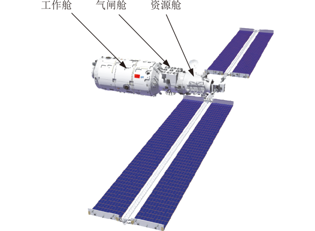
The resource cabins of experiment modules are located at the end of the whole module (Figure 3), and thrusters are mainly assembled there. The attitude and translation control is carried out by the balance of front and rear thrusters, resulting in serious attitude / translation coupling. Since the inertia level of the whole module determines the coupling characteristics of attitude / translation, the mass characteristic control of the whole module and the optimization layout of thrusters are also key factors in the design of the rendezvous and docking system.
Solution Method
Improve Rendezvous and Docking Control Dynamic Characteristics
The System Adopts the Secondary Expansion Scheme: After a comprehensive demonstration of multiple schemes, the solar wing of the experiment module adopts the two- step unfolding scheme: before the rendezvous and docking between the experiment module and the core module, the solar wing is deployed at a time of about 7m, and the power supply capacity of the single wing is greater than 1.5kW, to ensure that the rendezvous and docking control dynamics requirements are met. After the experimental module and the core module were axially docked, the solar wings were fully deployed twice to provide maximum power support for the space station assembly. The unfolding state of the solar wing of the experiment module is shown in Figures 4 & 5.
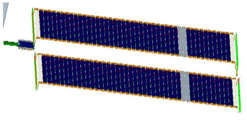
(a) Configuration before unfolding of solar array. (b) First step of unfolding process. (c) Final step of unfolding process.
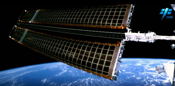
(a) Unfolding status in the first step (b) Unfolding status in the second step Figure 5: In-orbit unfolding of solar arrays on experiment module (in-orbit mission).
According to the flexible dynamic analysis, the fundamental frequency of the solar wing of the experiment module is greater than 0.2Hz under the first expansion state, and the stiffness characteristics are good. Through attitude control simulation, the flexible dynamic characteristics meet the rendezvous and docking control requirements of the experiment module when 7m is deployed at a time, and rendezvous and docking can be completed.
The in-orbit identification test of solar wing frequency was carried out in the flight mission of Wentian experiment module in July, 2022, and the main solar wing frequency was measured and identified in orbit. The deviation between the on-orbit measured value and the simulation results was better than 5% [13], greatly improved the attitude control of the space station.
Control the Quality Characteristics of the Whole Cabin in a Reasonable Layout
For cylindrical manned spacecraft with a large aspect ratio, the inertia of pitch/yaw axis is generally required to be more than 5 times greater than that of the rolling axis, so as to ensure that the thrust imbalance of the engine has less influence on the rendezvous and docking accuracy.
Because the inertia of the rolling shaft is highly sensitive to the control coupling, the key control is carried out. Based on simulation analysis, the moment of inertia of the rolling shaft was increased through reasonable optimization of equipment layout, and the engine layout and selection were optimized at the same time. The amplitude of rolling control torque was controlled to ensure that the design inertia of rolling axis was not less than 9×10⁴kg·m2 (not much smaller than inertia of other arises), and the level of rolling engine control torque was not more than 140Nm. The mass characteristic control of the whole experiment module can meet the requirements of each stage of the flight mission.
Optimize Rendezvous and Docking Control Scheme
The rendezvous and docking control scheme of the experiment module of the space station adopts Pulse width modulation (PWM) algorithm, and the structural filter is designed to suppress the vibration influence of the flexible solar wing. PWM is a normal algorithm in attitude control field. The impulse of the thruster is modulated by a series of pulses, and obtained the desired waveform (including shape and amplitude).
In the translation and convergence section of the rendezvous and docking process, the relative position and relative attitude six-degree of freedom control scheme is adopted, as shown in Figure 6. Since the laboratory module is far from the interface to the center of mass, the attitude motion has a great influence on the coupling motion of the interface’s transverse position. The attitude control effect is designed to be fed forward into the position control loop to eliminate the coupling effect of attitude control on the position motion.
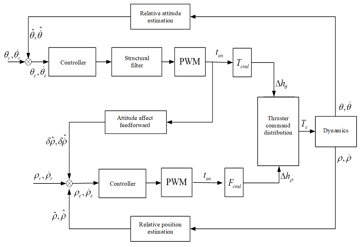
The function of translation-approach process is to guide the tracker to docking along the docking corridor and meet the initial conditions of docking, control the startup of the forward thrust or rail control engine, and assist the docking mechanism to complete the acquisition.
Through rendezvous and docking control shooting simulation of the experiment module, the attitude Angle
(a) Attitude angle (b) Attitude angular velocity control error of the experiment module in the moving and converging section is better than 2.5° and the attitude stability error is better than 0.2°/s when the solar wing is first expanded, as shown in Figure 7. The attitude control accuracy meets the rendezvous and docking control requirements.
In-orbit Implementation
Wentian experiment module and Mengtian experiment module adopted the all-phase fast rendezvous and docking scheme of “n circles +6 pulses”, as shown in Figure 8. Ground guidance software was used for the first time in China to calculate fast intersection strategy and inject flight control strategy [4]. By reserving n cycles of large phase chasing, 360° full phase chasing to the core module can be realized.
After being launched into orbit on July 24, 2022,
$$ = \mathrm {L i} + \mathrm {N a} ^ {+} $$
$$ = \frac {1}{2} $$ $$ \mathrm {法} = \mathrm {法} $$
$$ \mathrm {型} = \mathrm {型} $$
$$ = \frac {1}{2} $$ $$ - \frac {1}{2} $$
In-orbit test
launch Adjust
Phasing and transfer
Phase chasing
$$ = 1 $$ $$ - 1 $$
Orbit of CSS
$$ \mathrm {法} = \mathrm {法} $$
Chasing process
Ha of Entry point
$$ \mathrm {E} = \frac {1}{2} \mathrm {A} ^ {2} + \mathrm {B} ^ {2} $$
$$ \mathrm {C O} _ {2} + \mathrm {H} _ {2} \mathrm {O} = \mathrm {H C O} _ {3} + \mathrm {H} _ {2} \mathrm {O} $$ Entry point … … Hp of Entry point ≈3h ≈3.5h ≈4.5h ≈1.5h reserved Wentian Experiment module carried out six fast rendezvous pulses and then accurately switched to the autonomous control stage. It took 13 hours to complete rendezvous and docking with the core module, realizing the world’s first fast rendezvous and docking mission of a 23-ton class chasing spacecraft. After being launched into orbit on October 31, the Mengtian experimental module continued to adopt the fast rendezvous and docking scheme, and successfully completed the rendezvous and docking mission with the core module in 13 hours.
Autonomous control
$$ \mathrm {法} = \mathrm {法} $$
$$ - 1 $$ $$ = \frac {1}{2} $$
Phase adjustment
$$ - 1 $$ $$ = 1 $$
$$ = 1 $$ $$ \mathrm {型 形 形 形 形 形 形 形 形 形 形 形 形 形 形 形 形 形 形 形 形 形 形 形 形 形 形 形 形 形 形 形 形 形 形 形 形 形 形 形 形 形 形 形 形 形 形 形 形 形 形 形 形 形 形 形 形 形 形 形 形 形 形 形 形 形 形 形 形 形 形 形 形 形 形 形 形 形 形 形 形 形 形 形 形 形 形 形 形 形 形 形 形 形 形 形 形 形 形 形 形 形 形 形 形 形 形 形 形 形 形 形 形 形 形 形 形 形 形 形 形 形 形 形 形 形 形 形 形 形 形 形 形 形 形 形 形 形 形 形 形 形 形 形 形 形 形 形 形 形 形 形 形 形 形 形 形 形 形 形 形 形 形 形 形 形 形 形 形 形 形 形 形 形 形 形 形 形 形 形 形 形 形 形 形 形 形 形 形 形 形 形 形 形 形 形 形 形 形 形 形 形 形 形 形 形 形 形 形 形 形 形 形 形 形 形 形 形 形 形 形 形 形 形 形 形 形 形 形 形 形 形 形 形 形 形 形 形 形 形 形 形 形 形 形 形 形 形 形 形 形 形 形 Six-pulse maneuver $$
\mathrm {C O} {2} + \mathrm {H} {2} \mathrm {O} = \mathrm {H C O} {3} + \mathrm {H} {2} \mathrm {O}
$$ Docking Transfer to relative navigation chasing $$
\mathrm {法} = \mathrm {法}
$$ Quick R&D pulse entry Figure 8: Fast rendezvous and docking scheme of experiment module.
Module Transfer Control
The Wentian and Mengtian experiment modules of the space station rendezvous and dock axially with the core module respectively, and transfer the experiment module to the lateral berthing port of the core module through the in-orbit operation of module transposition, completing the in-orbit assembly of the three-module space station with “T” configuration. The assembly process is shown in Figure 2. Before the launch of the Mengtian experimental module, Wentan experimental module was transferred from the core module forward to the docking port to the IV quadrant berthing port, forming an “L” configuration. After the forward docking with the core module, the Mengtian experimental module is transferred from the forward docking port of the core module to the berthing port in quadrant II. The laboratory module transposition task takes the transposition mechanism as the main component, and the large mechanical arm as the backup [14].
Technical Problem
The most critical task in the assembly and construction of the space station is the experimental module segment transposition, which is the core key technology that needs to be broken through and mastered. During the development of the space station, the design of the module transposition system is faced with great challenges. There are three main problems:
The design of the system should consider the requirements of rendezvous and docking and the requirements of the integrated use of the resources of the assembly after transposition The three modules of the Tiangong Space Station are designed in a unified way, and each module has its focus on tasks. The two experiment modules must meet the requirements of rendezvous and docking missions, as well as the requirements of long-term flight of the assembly, and the resources of the three modules shall be used together after the transfer of the experiment module, including: After the rotation, the attitude sensor and measurement and control antenna of the experiment module can still be guaranteed to continue to be used. The orientation of the experiment module can meet the requirement of space application loads pointing from the sky to the Earth. The exit hatch of the airlock cabin of the experiment module remains oriented towards the Earth.
During the transfer period of the experiment module, each aircraft cannot actively control its attitude In the design stage of the space station scheme, commercial software and finite element models were used to establish the models of the rotating mechanism, mechanical arm and flexible solar wing, and the flexible multi-body dynamics model of the cabin body rotating process after the load experiment module was established. The dynamic simulation shows that the fundamental frequency of the assembly and the flexible solar wing are about 0.02Hz and 0.05Hz respectively after the 23t experimental cabin body loaded by the rotating mechanism or mechanical arm, which belong the most vulnerable flexible system state. The dynamic characteristics of complex multi-flexible bodies with very low frequency are extremely unfavorable to the design of the rotating system scheme and control scheme.
On the other hand, through the analysis of the load capacity of the butt mechanism, the indexer mechanism and the manipulator, it is found that the anti-load capacity of the butt mechanism, the indexer mechanism and the manipulator during the working period of the mechanism is weak, requiring the GNC control torque not to exceed 100Nm, which makes the design and implementation of the GNC control scheme extremely difficult, because during the indexer period, As long as the experimental module and the core module assembly has a slight control incentive, it may lead to the amplification of the amplitude of the attitude of the whole station and the flexible solar wing. GNC active control will produce a large control torque, which will cause damage to the butt mechanism, rotation mechanism, mechanical arm and other mechanism products. If CMG is used for attitude stability control, the change of assembly’s mass characteristics, gravity gradient torque and aerodynamic torque will lead to angular momentum saturation of CMG, and the angular momentum unloading must be carried out by the thrusters, which will cause damage to moving parts of mechanism products.
Therefore, an attitude active stop-control scheme must be adopted in the process of module rotation to reduce the excitation load during the process of module rotation, and the space station must complete module rotation in the free- floating state.
Attitude Drift is too Large, Resulting in Intermittent Measurement and Control
During the design of the system scheme, the duration of the shift of the experimental cabin segment should be designed according to 100 minutes.
A flexible multi-body dynamic model was established to carry out a simulation analysis of the laboratory module rotation process. After starting the module rotation under a three-axis stable attitude to the ground, the assembly was in a free-floating state, which was mainly affected by environmental interference moments such as gravity gradient moment and atmospheric drag moment. Can cause both combination roll axis and yaw axis is greater than 360°, pitching axis is greater than 180° attitude drift, lead to transfer during the measurement and control, off and on for task safety reliability.
Solution method
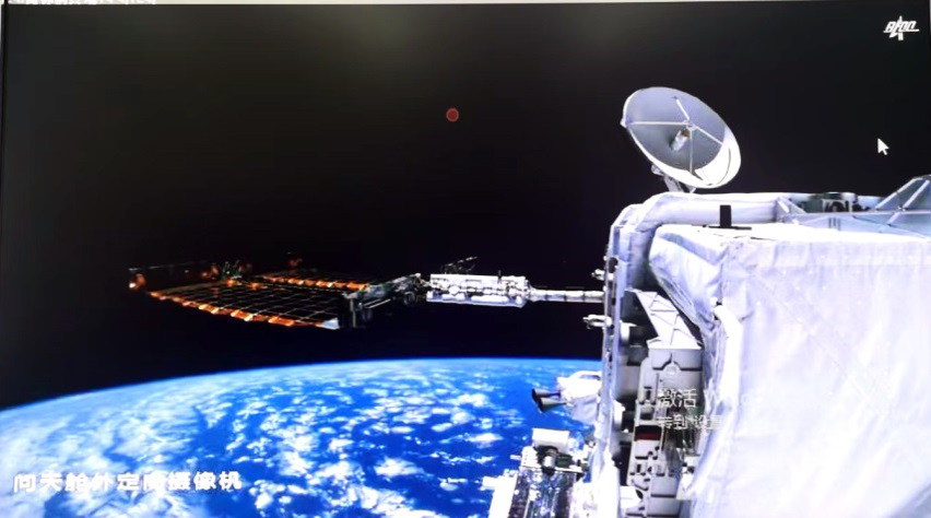
The Space Station Adopts the Plan of Plane Transposition: To take into account the rendezvous and docking requirements of the experiment module and the resource integration requirements of the experiment module after the transfer, the Tiangong Space Station adopts the “planar” transfer scheme, that is, the experiment module and the core module are in a plane during the transfer process, as shown in Figure 9. In the space station system, a new two-degree- of-freedom roving mechanism is developed. The roving arm of the roving mechanism is configured in the experiment module, and the base of the roving mechanism is configured in the node module of the core module to realize the planar module roving. At the same time, a large mechanical arm is designed as a backup for the module rotation task [13].
![Figure 8: Ground guidance software was used for the first time in China to calculate fast intersection strategy and inject flight control strategy [4]. By reserving n cycles of large phase chasing, 360° full phase chasing to the core module can be realized.](/fulltextimages/13351/fig_8.png)
![Figure 9: In the space station system, a new two-degree- of-freedom roving mechanism is developed. The roving arm of the roving mechanism is configured in the experiment module, and the base of the roving mechanism is configured in the node module of the core module to realize the planar module roving. At the same time, a large mechanical arm is designed as a backup for the module rotation task [13].](/fulltextimages/13351/fig_9.png)
Passive Stable Based on Gravity Gradient
The development team of the space station has continued to tackle key technologies with simulation accuracy as the starting point when solving the difficult problem of module rotation control.
The first step focuses on the modeling and simulation of cabin transposition dynamics to establish an accurate and reliable simulation model of cabin transposition dynamics.
Through concentrated research, several key technologies such as parameterized analysis of variable environmental disturbance torque, flexible multi-body dynamics modeling, and model reconstruction of variable configuration assembly have been broken through, and a joint simulation software for dynamics and control of space station assembly with independent intellectual property rights has been developed. The software architecture is shown in Figure 10. Various commercial software was used to compare and verify the correctness of the dynamic simulation model of the transposition task [15].
The second step is to organize the whole system and subsystems to carry out coordinated research and optimize the control scheme of module rotation. The optimization goal is to minimize the attitude drift of the entier station during module rotation and to continuously see the surface measurement and control.
Based on the analysis of mass characteristics of the composite mass through comprehensive demonstration of multiple schemes and a large number of simulation analyses, a passive stable rotation scheme was proposed which made full use of gravity gradient moment and atmospheric drag moment as balance moment [16]. Its core design idea was to draw on the pendulum stability principle to stand the composite mass upright and use gravity gradient moment to stabilize the Earth’s axis. Then, based on the stability principle of the sail rudder, the assembly flew at the minimum windward side and rotated backward. The yaw axis was stabilized by the atmospheric drag moment generated by the solar wing of the experiment module, so as to achieve the passive stability control effect of the three-axis attitude during the module rotation.
The simulation results depicted in Figure 11 show that the attitude drift of the assembly can be reduced by one order of magnitude by adopting the gravity gradient passive stable control of the transposition scheme, and 100% measurement and control coverage can be achieved during the transposition process, effectively eliminating the technical risks during the cabin transposition process [13].
| Gravity gradient mode | Movement statu of assembly | s Joint simulation scheduling mode | Movement status of assembly | Atmospheric drag mode | |||
|---|---|---|---|---|---|---|---|
| Gravity gradient moment | Atmospheric drag moment |
![Figure 10: Various commercial software was used to compare and verify the correctness of the dynamic simulation model of the transposition task [15].](/fulltextimages/13351/fig_10.png)
(a) Model for module transferring simulation (b) Attitude comparison between simulation and data in-orbit Figure 11: Simulation model and attitude curve in transferring process of Wentian experiment module.
In-orbit implementation
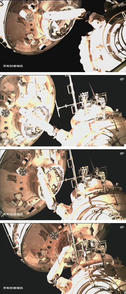
Before the experiment module transfer mission, the in-orbit flight test of the robotic arm transfer mission was carried out with the cargo spacecraft on January 6, 2022. The in-orbit attitude of the assembly was consistent with the results predicted by the simulation. The flight verification of the experiment module transfer scheme and dynamic simulation model was carried out, and the simulation model was further refined through the in-orbit data. On September 30, 2022 and November 3, 2022, the in-orbit transfer tasks of the Wentian Experiment module and the Mengtian
Experiment module were completed successively, as shown in Figure 12.
were continuous and normal, the error of the space station attitude simulation predicted and the in-orbit result was better than 4%, the experiment module transfer mission was a complete success, and the in-orbit assembly of the T-shaped space station was completed.
During the experiment module transfer, the assembly attitude was stable, the ground measurement and control
Variable Configuration Assembly Control Technical Problem
Assembly Fusion Control According to the mission planning of the Tiangong Space Station, the space station can undergo 53 normal and emergency configurations in orbit, which is a complex system with variable configurations.
The Tiangong Space Station consists of a three-module independent vehicle that adopts rendezvous, docking and module rotation technologies to form an organic assembly. The three-module is equipped with 27 gyro components, 10 star sensors, 12 CMGS and more than 100 attitude and orbit control engines. The control system of the core module and the sky experiment module is not only responsible for the attitude and orbit control during the flight of each module, but also responsible for the attitude and orbit control function of the assembly. It makes full use of the existing control resources of the third module in orbit to realize the high reliability of the space station, which makes the design of the control system extremely complicated.
Angular Momentum Management of the Space Station When the composite flies for a long time, the long-term accumulation of atmospheric drag moment and gravity gradient moment will lead to the saturation of CMG angular momentum, which requires the unloading of CMG angular momentum.
Conventional unloading methods include magnetorquer unloading and jet unloading. The system scale of the space station is too large. If the magnetic torque of the triaxial magnetorquer is used for unloading, the magnetic moment of the triaxial magnetorquer must exceed 10000A·m2, which is difficult to be realized by the current technology. CMG will be saturated and jet unloading of the engine will be too frequent when the space station flies for about 3 cycles in a triaxial stable attitude to the earth. As the moment of inertia of the space station is 106 kg·m2, it is used for angular momentum unloading, engine life and propellant consumption are huge, which is unacceptable to the project.
Therefore, both magnetotorquer or air jet control are not suitable for angular momentum management during long- term flight of the space station, and three-axis stable attitude is not suitable for long-term flight attitude. Therefore, a new angular momentum management scheme and long-term flight attitude of the space station need to be designed.
Solution Method
Adopt an integrated attitude and orbit control scheme to realize information fusion of the three cabins The integrated attitude and orbit control scheme is adopted to control the assembly of Tiangong Space Station. The modular and bus-based design of the control system of each module enables the integrated use of resources of each module, so as to improve the system reliability of the whole station, reduce simple equipment redundancy, and achieve the optimal overall performance of the space station. The control system architecture of Tiangong Space Station is shown in Figure 13. The control computer, sensor, actuator, propulsion control driver and power drive controller of each cabin are directly connected through the standard 1553B data bus. The control system of the core module is the main component, and the control system of the Wentian experiment cabin is the backup to realize the unified call of control resources of each cabin and the fusion of information. During the docking of the cargo spacecraft, the space station invokes the cargo spacecraft attitude orbit control engine and propellant through the standard 1553B data bus for integrated attitude orbit control.
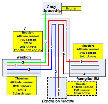
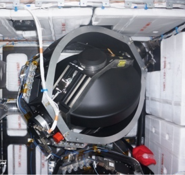
There are two kinds of attitude control methods: CMG control and engine jet control. CMG control is the main part and jet control is the backup. One set of CMGS (6 per set, a total of 12) is installed in the Tianhe core module and the Tianhe experimental module respectively, which are respectively arranged outside and inside the cabin. According to the specific requirements of angular momentum control in different flight attitudes, one set of CMGS is planned to start up or two sets of CMGS are planned to start up at the same time.
Angular Momentum Management Techniques
Mir Space Station adopts an inertial system attitude for stable flight. The inertial main axis is perpendicular to the orbital plane, and the gravity gradient moment and aerodynamic moment almost do not accumulate. Therefore, it is required that the inertial main axis in the orbital plane should be as close as possible and the space station’s windward area should be as small as possible, so as to ensure that the angular momentum fluctuation on the inertial main axis perpendicular to the orbital plane is within the CMG angular momentum envelope. The International Space Station adopts the torque balance attitude for long-term flight, and makes full use of the gravity gradient moment generated by the inertia difference of the main inertia axis to carry out continuous angular momentum unloading of the aerodynamic moment, avoiding the use of engine air injection. When the gravity gradient moment is greater than the aerodynamic moment, the angular momentum can be unloaded by adjusting the attitude Angle and using the gravity gradient moment.
Tiangong Space Station takes attitude control, propellant saving, energy demand, measurement and control support, and space-to-earth application requirements into consideration. It adopts an orbital torque balance attitude for long-term flight and uses gravity gradient torque to achieve CMG angular momentum management. In a steady state, the rolling axis swings from side to side within one orbital period, and the pitching axis is in a constant attitude bias state. The range of rolling shaft swing and pitching shaft bias is determined by the gravity gradient moment and aerodynamic moment. Torque balance attitude flight of orbital system can effectively avoid using engine jet to consume propellant and rationally utilize engine in-orbit service life.
A physical simulation test of angular momentum management and control technology was carried out on the ground to verify the correctness of the angular momentum management algorithm of the space station assembly.
In-Orbit Implementation
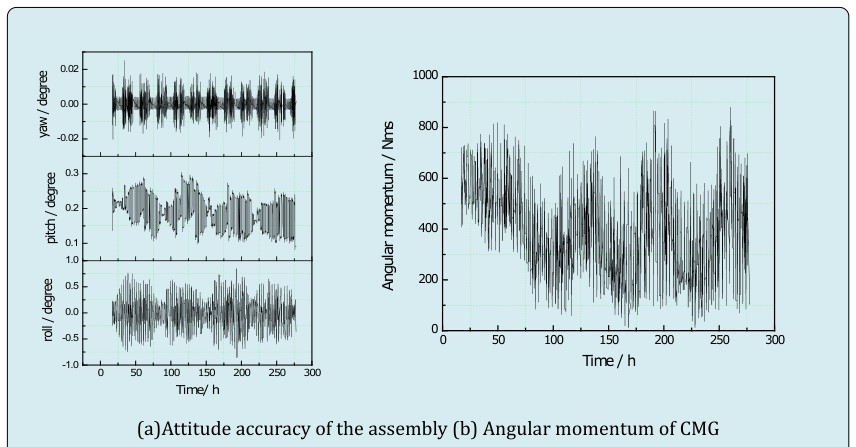
In the stage of key technology verification and assembly and construction of the space station, there were 11 Launch missions, and the space station assembly went through 17 configurations. After the in-orbit flight verification, the functional performance index is better than the index requirements, and the control scheme of the variable configuration assembly based on the multi-module information fusion based on the 155B bus is correct. After the assembly and construction of the third module of the space station was completed in November 2022, in-orbit tests of the torque balance attitude and angular momentum management algorithm of the orbiting system were carried out immediately. The results are shown in Figure 15. The results show that the attitude of the composite is stable, the CMG angular momentum remains stable for a long time without accumulation, and the angular momentum management algorithm of the space station is correct.
The assembly and construction of the Tiangong Space Station is an orderly combination of flight events such as single module flight, module transfer and assembly flight according to mission planning. The space station has a large scale, complex system and extremely complex dynamic characteristics. During the design and development of the space station, many difficult challenges in dynamics and control were encountered. The research team overcame these difficulties, broke through and mastered all the key technologies of the manned space station, and achieved complete success in the mission of key technology verification stage and assembly and construction stage, completing the assembly and construction of the space station. The space station assembly is stable in orbit and in good condition.
In this paper, the main problems and challenges in the design and control schemes of each mission system are reviewed for the rendezvous and docking mission of the laboratory module, the transfer mission of the laboratory module and the long-term flight mission of the assembly, and the engineering solutions adopted by the developers are briefly described, and the in-orbit flight results are briefly introduced, hoping to provide useful inspiration for the development of subsequent engineering models.
Acknowledgment
Funding: This work was supported by China Manned Space Engineering Office. Author contributions: ZHANG Qiao is the corresponding author and is responsible for data analysis. LUO Wencheng conducted the literature review and paper revision. SHI Jixin and LUO Chao offered many valuable help and suggestions. Competing interests: The authors declare that they have no competing interests. Data Availability: The data used to support the findings of this study are available from the corresponding author upon reasonable request
References
-
Jianping Z (2013) Chinese space station project overall vision. Manned Spaceflight 19(2): 1-10.
-
China Manned Space Engineering Office (2016) Development of space station engineering. China Manned Space Engineering Office, China.
-
Xiang W, Wei W (2021) Key Technical Characteristics of the Tiangong Space Station. Scientia Sinica Technologica 51(11): 1287-1298.
-
Xiang W, Qiao Z, Wei W (2022) System Characteristics and Prospect of China Space Station. Spacecraft Engineering 31(6): 26-39.
-
Guangchen Z (2022) Development on Configuration Technology of China Manned Spacecraft. Spacecraft Engineering 31(6): 46-53.
-
Dongming G, Wencheng L, Runran D (2022) Flexible Multi-body Dynamics Modeling and Simulation for Space Station System. Spacecraft Engineering 31(4): 8-15.
-
Yang H (2018) The “Tiangong” Chinese Space Station Project. Front Eng Manag 5(2): 278-283.
-
Yang H, Zhang Q (2018) Introduction to Manned Environment and Scientific Experimental Resources of China Space Station. Proceedings of the 69th International Astronautical Congress, Paris: IAC.
-
Sorokin IV, Markov AV (2008) Utilization of space stations: 1971-2006. Journal of Spacecraft and Rockets 45(3): 600-607.
-
Evans CA, Robinson JA, Tate-Brown J, Thumm T, Crespo- Richey J, et al. (2008) International Space Station Science Research Accomplishments during the Assembly Years: An Analysis of Results from 2000-2008. NASA/TP-2009- 213146. NASA, USA.
-
Giblin TW (2010) The International Space Station: Systems & Science, 20100018503. NASA, USA.
-
Stockman B, Boyle J, Bacon J (2010) International Space Station Systems Engineering Case Study, ADA538763. Air Force Center for Systems Engineering, USA.
-
Xiang W, Qiao Z, Wei W (2023) Design and Application Prospect of China’s Tiangong Space Station. Space: Science Technology 3: 0035.
-
Daming L, Wei R, Hu Chengwei (2014) Key technology review of the research on the space station manipulator. Manned Spaceflight 20(3): 238-242.
-
Tao X, Lefeng S, Wei W, et al. (2021) Digital space station dynamic and control simulation modeling and flight control application. Aerospace Control and Application 47(5): 40-47.
-
Jixin S, Dongming G, Jingyan F (2019) Dynamic analysis modeling of large complex spacecraft based on fixed- interface modal synthesis and its software. Spacecraft Environment Engineering 36(4): 318-332.
- Early Universe: Hadronic Crystals Coherent Micro Gravitational Wave Emitters PHYSICS Part II
- The Solar System Constraint Maze: A Scientific Dead-End Revealing the Interuniversal Machine
- Assessment of Radiofrequency Radiation from 2G and 3G Mobile Phone Handsets
- Early Universe Magneto-Gravitational Coupling Genesis Physics: Part I
- Falsifiability of the Classical Law of Gravitation and Unveiling the Time-temperature Entanglement of the Universe
- Origin of Ancient Civilisations The Southern Hemisphere’ Scenario