Stiffness Comparisons of SOP Interlocking Plate Configurations in 3D Printed Canine Lumbosacral Vertebrae
There are no published biomechanical studies evaluating the effect of stabilization techniques on the stability of the 3D printed models of the canine lumbosacral junction. The purpose of the study was to quantify stiffness of String of Pearls (SOP) interlocking plating system on the lumbosacral junction in dogs. Testing was performed on five canine lumbosacral junction 3D printed models. Four-point bending was applied and displacement along the ventral aspect of the lumbosacral junction measured. Stiffness of six stabilization techniques was tested: Models with contiguous polymer reconstruction articular facets. Models with two dorsal SOP plate each with two pedicle screws in L7, two sacral screws and contiguous polymer reconstruction articular facets. Models with two SOP plates with two L7 pedicle screws, two sacral screws and disarticulated L7-S1 articular facets. Models with two SOP plates with only the caudal L7 pedicle screw and two sacral screws and disarticulated L7-S1 articular facets. Models with two SOP plates with only the cranial L7 pedicle screw, two sacral screws and disarticulated L7-S1 articular facets. Models with one SOP plate, with two pedicle screws in L7 and two sacral screws and disarticulated L7-S1 articular facets. The greatest stiffness was obtained in models with contiguous polymer reconstruction articular facets stabilized by two SOP plates with two screws engaging the pedicle of L7 (90.13 ±11.16 N/mm). There was no difference in gap stiffness between models with two SOP plates and disarticulated articular facets (54.43 ± 6.25 N/mm), and models with two SOP plates and only a cranial L7 pedicle screw (42.01 ± 8.64 N/mm). The lowest stiffnesses was recorded in constructs with two SOP plates and a caudal L7 pedicle screw (26.38 ± 4.56 N/mm) and one SOP plate (26.94 ±5.83 N/mm) and intact models, contiguous polymer reconstruction articular facets, with no stabilization technique applied to the lumbosacral junction (16.16 ± .89 N/mm). The study-demonstrated stiffness using a single cranial pedicle screw in the pedicle of L7 was no different from models with two pedicle screws in L7. Contiguous polymer reconstruction articular facets had a constructive effect on overall stiffness of the lumbosacral junction.
Introduction
The canine lumbosacral (LS) junction is a functional vertebral unit that can be afflicted with pathologic conditions, including Hansen type II disc degeneration, ligamentous hypertrophy, articular facet and joint capsule hypertrophy, spondylosis deformans, subluxation of the sacrum, and lumbosacral instability or instabilities, which are collectively referred to as Degenerative Lumbosacral Stenosis (DLSS) [1, 2, 3, 4, 5, 6]. Surgical management, decompression, and stabilization techniques are commonly used for the treatment of canine patients with moderate to severe clinical signs of DLSS [7]. Multiple dorsal stabilization techniques have been described and implemented with similar clinical success. The commonly used stabilization techniques of the LS junction are (1) bilateral transarticular facet screws and (2) pins or screws and polymethylmethacrylate (PMMA) [6, 7, 8, 9, 10]. Advantages of the P/PMMA technique may require less soft tissue dissection for implant placement and shorter segments of vertebral column to be stabilized. P/PMMA method may use fewer implants, four to six threaded pins with PMMA [6, 7, 8]. Biomechanical studies provide evidence that fixation via P/PMMA or SOPTM interlocking plates provide similar stability for L7-S1 vertebrae stabilization [6, 10]. The P/PMMA construct while thicker and bulkier is in more intimate contact with the vertebrae providing a buttress stabilization, which likely contributed to the more stable appearance of this group. Intra-operative and post-surgical complications have been described for both techniques, and they include fracture of the L7 articular facet, poor implant positioning, nerve root damage, and implant failure associated with the bilateral transarticular facet screw technique. Complications of using PMMA include thermal injury, increased risk of infection, and bulk/mass effect of acrylic on impeding surrounding soft tissue closure [3, 11]. To overcome some of these difficulties, Meheust, et al. described the pedicle-screw-rod fixation technique for LS stabilization. Pedicle screws are dorsally inserted in L7 and S1. Titanium rods are used to connect the pedicle screws and provide internal stabilization. Although this surgical technique enables veterinary surgeons to overcome the complications of using PMMA, it is technically challenging and can have several complications associated with improper placement of the pins/screws and implant failure. The recently developed SOPTM Locking Plate System (SOP) combines the advantages of a fixed angle stabilization system, like P/PMMA system, with a significantly lower profile. The SOP plate can be contoured in multiple planes of twisting and bending so that the locked screws are directed into the limited available bone stock [12]. The SOP locking plate system is affordable and has unique advantages compared with other locking plate systems in this application [13]. The SOPTM interlocking plate technique may require more contouring and the placement of eight to ten screws, thereby lengthening surgical time [10]. Clinically, this SOP interlocking plate system has been used to stabilize the canine LS junction by placing two screws in the L7 pedicles and screws in the sacrum [14] (Figure 1). However, biomechanical studies have not extensively investigated the use of the SOP system for LS junction fixation. Therefore, the application of LS stabilization with the SOP plate system has not been optimized for vertebral segment stabilization; the placement and quantity of the screws and the status of the L7-Sacral articular facets have yet to be determined [6]. A major complication of techniques that utilize pedicle screw fixation is impingement of the L7 nerve root and penetration into the vertebral canal. The success of these techniques depends on accurate insertion of the pedicle screws. Therefore the placement of two screws in the pedicle of L7 is likely to be more difficult than inserting only one [15, 16]. Some adaptations of pedicle screw systems describe one screw in L7 [15]. However, the use Open Access Journal of Veterinary Science & Research
of two screws with the SOP system may be necessary to achieve adequate biomechanical stability of the LS junction and longevity of implant. The purpose of this study was to quantify the stiffness of different SOP interlocking plate system configurations on LS stabilization. We hypothesized that 1) two dorsal SOP interlocking plates would provide greater stiffness than a single plate and that 2) two L7 pedicle screws would provide greater stiffness than a single L7 pedicle screw.
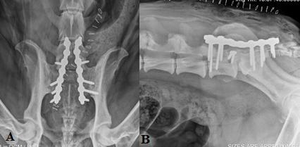
Figure 1: Postoperative radiographs of the SOP stabilization technique. Postoperative dorsoventral (A) and lateral (B) radiographs of a 3 year old spayed female Bloodhound weighing 107 lbs diagnosed with degenerative lumboscaral stenosis. The lumbosacral junction was stabilized with two seven hole 3.5mm SOP locking plates placed across the LS junction. Each plate was secured in place by two screws engaging the pedicle of L7 and three screws engaging the sacrum. The L7-S1 articular facets were stabilized with 2.7mm screws.
Materials and Methods
Canine Lumbosacral Vertebral Model Construction
Five identical, 3Dcanine LS vertebral models from L3 through the pelvis were constructed for each condition tested in the study (Figure 2). The vertebral models were designed based on a computed tomography (CT) scan of a 3-year-old male neutered beagle weighing 16 kg. This dog, which did not have radiographic or clinical evidence of DLSS, underwent CT scans for reasons unrelated to the study. The dog was imaged using a 16-slice helical multi detector CT scannera. Slice thickness was 0.5 mm, and all images from the series were used to develop the 3D vertebral models. The images were exported to a picture archiving and communication system server. The Digital Imaging and Communications in Medicine images were a TSX-201A, Toshiba America Medical Systems Inc., Tustin, CA imported into an imaging processing applicationb and the region of interest was post processedc, cropped, and exported for printing.
![Figure 2: Lumbosacral 3D Models. Dorsal-lateral (A) and ventral (B) views of the 3D model of the canine lumbosacral spine used for this study. The vertebral models were printed using CT scan information of a 3- year-old neutered male Beagle using ABS polymer. The canine vertebral models were generated using a 3D printerd, an additive manufacturing method in which an object is created by depositing powdered material in layers that are then selectively joined with a binding polymer from an inkjet print head. Each layer represents a thinly sliced horizontal cross-section of the sample object [17]. The vertebral models were printed with acrylonitrile butadiene styrene (ABS), a production-grade thermoplastic polymer with an elastic modulus or a Young’s modulus of 2.4 GPa. The elastic modulus of trabecular bone ranges from 0.01 to 10 GPa, and that of dense cortical bone is approximately 11GPa, thus placing the elastic modulus of ABS within the range of that cancellous bone and somewhat lower than that a cortical bone [11]. The vertebrae were printed with solid ABS. The resolution of the printer was 0.25 mm. We chose ABS because of its elastic modulus, ability to be printed, and ability to be machine worked. ABS can be drilled and tapped, and screws can be removed and replaced without visible disruption to the model or material. All models were printed in the same orientation to ensure consistency in reconstruction. The vertebral models were rendered with Hounsfield units for bone (+700 [cancellous bone] to +3000 [dense bone]) with no soft tissue components, and the intervertebral discs and the ligamentous and joint capsule were excluded from being rendered or printed. The articular facets were printed as contiguous polymer reconstruction units. All bone was printed with homogenous ABS without maintaining gradients of bone density and with no differentiation between cortical and cancellous bone.](/fulltextimages/1306/fig_2.jpeg)
Figure 2: Lumbosacral 3D Models. Dorsal-lateral (A) and ventral (B) views of the 3D model of the canine lumbosacral spine used for this study. The vertebral models were printed using CT scan information of a 3- year-old neutered male Beagle using ABS polymer. The canine vertebral models were generated using a 3D printerd, an additive manufacturing method in which an object is created by depositing powdered material in layers that are then selectively joined with a binding polymer from an inkjet print head. Each layer represents a thinly sliced horizontal cross-section of the sample object [17]. The vertebral models were printed with acrylonitrile butadiene styrene (ABS), a production-grade thermoplastic polymer with an elastic modulus or a Young’s modulus of 2.4 GPa. The elastic modulus of trabecular bone ranges from 0.01 to 10 GPa, and that of dense cortical bone is approximately 11GPa, thus placing the elastic modulus of ABS within the range of that cancellous bone and somewhat lower than that a cortical bone [11]. The vertebrae were printed with solid ABS. The resolution of the printer was 0.25 mm. We chose ABS because of its elastic modulus, ability to be printed, and ability to be machine worked. ABS can be drilled and tapped, and screws can be removed and replaced without visible disruption to the model or material. All models were printed in the same orientation to ensure consistency in reconstruction. The vertebral models were rendered with Hounsfield units for bone (+700 [cancellous bone] to +3000 [dense bone]) with no soft tissue components, and the intervertebral discs and the ligamentous and joint capsule were excluded from being rendered or printed. The articular facets were printed as contiguous polymer reconstruction units. All bone was printed with homogenous ABS without maintaining gradients of bone density and with no differentiation between cortical and cancellous bone.
b OsiriX, Pixmeo, Bernex, Switzerland c NetFabb Studio Basic 4.9.5, Lupburg Germany d Stratasys uPrint, Stratasys Inc., Eden Prairie, MN
Open Access Journal of Veterinary Science & Research
Instrumentation of Locking Plates
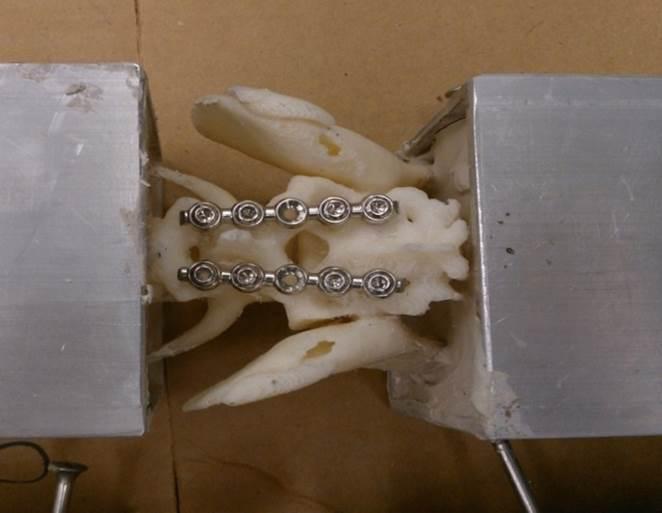
All vertebral models were instrumented with a five node (pearl) 2.7mm SOP interlocking platese. Rongeurs were used to remove a small portion of the model, caudal to the L6-L7 articular facet, to improve plate placement adjacent to the bone. None of the SOP locking plates was contoured. A 2.0-mm drill bit was used to drill pilot bicortical holes into the vertebral models, and the holes were tapped with a 2.7-mm tap. Standard 2.7-mm cortical screws were used in the SOP plate system and model testing. The specimens were plated with two screws in the pedicles and body of L7 and two screws in the body of the sacrum as shown in Figure 3. The screws did not penetrate the vertebral canal or intervertebral foramina. The center node of the five-node plate was left empty.
Gap Stiffness and Bending Moment Stiffness
To perform gap stiffness and bending moment stiffness testing using a material testing frame, the vertebral models were potted within two segments of aluminum square tubing. Each segment of tubing measured 15.2 cm × 7.6 cm × 7.6 cm (length × width × height) and 3 mm in thickness. The vertebrae were fixed so that the two pieces of aluminum tubing were separated by 6 cm. This positioning enabled the region extending from the caudal aspect of the L6 to the S3 vertebrae to be open to apply stabilization techniques. Four self-tapping screws were placed across the aluminum tubing to initially secure the 3D printed models in position. Cranially, the lumbar e Orthomed Ltd., West Yorkshire, UK vertebrae were stabilized by screws drilled through L4 and L5, with each screw entering from opposite sides. Two screws were placed through the center of the acetabulum on both sides of the pelvis to stabilize the caudal portion of the spine. Once stabilized in the desired position, the model was potted using Bondo Professional Body Repair, a polyester resin mold. The vertebral model was held against a frame to ensure alignment while the resin solidified. Stiffness of the models and the SOP locking plates was assessed using a material testing framef. The vertebral models were subjected to four-point bending. Each model was placed on two outer support rollers that were 12.5mm in diameter and 27cm apart. The inner rollers of the load frame were set to a gap of 9cm (Figure 4). Four- point bending the enabled symmetrical application of the force over the specimen while creating a bending moment at the center (LS junction) of the specimen [12]. The material testing frame parameters, movement of load/actuator, and data collection were processed using a custom built program.
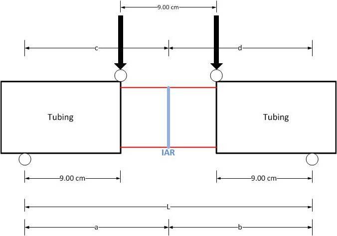
Figure 4: Schematic of the 4-point bending and setup of the vertebral model loaded in the material testing frame. Support rollers are located at the ends of the tubing. Distance between the rollers (L) is 27cm. The load frame rollers (downward arrows) apply symmetrical force on the edges of the tube and were separated by 9cm. The instantaneous axis of rotation represents the central axis of the setup. Distance from the support rollers to the instantaneous axis of rotation (a, b, c, d) is 13.5cm. An extensometerg, secured to the ventral aspect of the S1 vertebrae, was used to record gap displacement over the LS junction. To secure the extensometer in position, f TestResources, Shakopee, MN g 3542-0125M-025-ST, Epsilon Technology Corp., Jackson, WY
Open Access Journal of Veterinary Science & Research
two wooden dowels were placed in 2mm holes drilled into either side of the ventral aspect of the LS junction and glued in place. The extensometer was then glued onto the dowels. The pre-load applied for the vertebral model testing was 1.5N. The force-applying actuator moved at a rate of 1 mm/sec for a total displacement of 5mm. The 5mm deflection was chosen based on preliminary studies that showed the models only elastically deformed; no plastic deformation or destructive bending occurred. A total of 600 data points were collected for each test cycle. The vertebral model was initially tested intact and then with five different configurations of the SOP locking plate system. Articular facets were separated using a Micro 100 reciprocating saw for constructs 3-6. Constructs were tested in the following order:
- Intact vertebral model with contiguous polymer reconstruction articular facets in the absence of any fixation.
- Vertebral model with two SOP locking plates, two screws engaging the pedicle of L7 and two screws engaging the sacrum.
- Vertebral model with disarticulated L7-S1 articular facets and two SOP plates with two screws in the pedicle of L7 and two screws in the sacrum.
- Vertebral model with disarticulated L7-S1 articular facets, two SOP plates with the cranial L7 pedicle screw omitted and the caudal L7 pedicle and two sacral screws in place.
- Vertebral model with disarticulated L7-S1 articular facets, and two SOP plates with the cranial pedicle screw engaging the pedicle of L7 and the caudal L7 pedicle screw omitted and two screws in the sacrum.
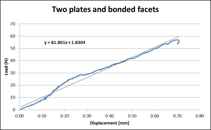
- Vertebral model with disarticulated L7-S1articular facets, with only one SOP plate placed with two screws in L7 and two screws in the sacrum. Data from the load cell and extensometer were used to calculate gap stiffness and bending moment stiffness. Data were exported to a spreadsheet programh and used to generate load-displacement curves and calculate the slope using the Excel slope function (Figure 5). The slope of the line represents the gap stiffness (N/mm). The bending moments of the different constructs were determined using the following formula:
M = (F × a × d)/L Where M is the bending moment (Nm), F is the force applied on the model (N), a and d are the distances from the center of the support rollers to the instantaneous axis of rotation (IAR; center of the setup), and L is the distance h Microsoft Excel, Microsoft Corporation, Redmond, WA between the support rollers (m). The bending moment- displacement curves were graphed, and bending moment stiffness (Nm/m) was determined from the slopes. Mean gap stiffness and bending moment stiffness for each of the constructs were calculated and reported along with standard deviations and 95% confidence intervals. Normality of the data was tested and verified using the Shapiro-Wilk test. Statistical significance of the results was evaluated with statistical softwarei using ANOVA followed by a Tukey honest significant difference (HSD) post-test performed at P<.05.
Results
Gap Stiffness and Bending Moment Stiffness
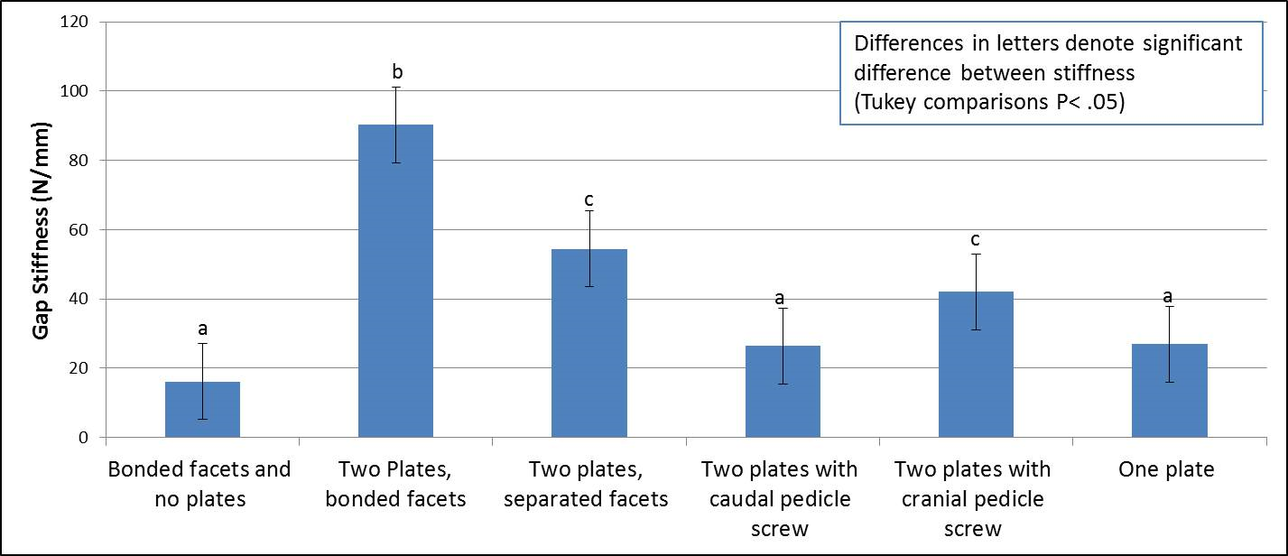
The standard deviation of the stiffness data ranged from 5% to 21% of the mean stiffness. The vertebral model variances were comparable with similar studies using cadaveric models [11, 18, 19]. The mean gap stiffness of vertebral construct #2 with contiguous polymer reconstruction articular facets and two plates with all screws engaged measured 90.2 ± 11.2N/mm and the bending moment stiffness of this construct was6130.7 ± 775.0Nm/m, which was significantly higher than those of other groups. The mean gap stiffness and bending moment stiffness of construct #3 with disarticulated facets, stabilized with two plates and all screws engaged was not significantly different from those of construct #5 stabilized by two plates with only the cranial pedicle screw (P >.05 ) (Table 1). The gap stiffness and bending i GraphPad, Version 4, Software, Inc., La Jolla, CA
Open Access Journal of Veterinary Science & Research
moment stiffness of these two constructs were significantly greater than those of the remaining constructs were. The intact vertebral model #1 without plates (gap stiffness 16.2 ± 0.9N/mm and bending moment stiffness 1081.8 ± 68.5 Nm/m), construct #4 with two plates and only the caudal screw in the pedicle of L7 (gap stiffness 26.4 ± 4.6N/mm and bending moment stiffness 1781.4 ± 307.6 Nm/m), and construct #6 with only one plate (gap stiffness 26.9 ±5.8 N/mm and bending moment stiffness 1803.7 ± 395.6 Nm/m) had mean gap stiffness and bending moment stiffness measurements that were not statistically different from each other and lower than those of other constructs (Table 1 and Figure 6).
| Construct | Gap Stiffness (N/mm) | Bending moment stiffness (Nm/m) | ||||||
|---|---|---|---|---|---|---|---|---|
| Intact specimen | 16.16 ± .89a | 1081.76 ± 68.50a | ||||||
| Two Plates with intact facets | 90.22 ± 11.16b | 6130.68 ± 775.01b | ||||||
| Two plates, separated facets | 54.43 ± 6.25c | 3673.78 ± 422.09c | ||||||
| Two plates with caudal pedicle screw | 26.38 ± 4.56a | 1781.40 ± 307.59a | ||||||
| Two plates with cranial pedicle screw | 42.01 ± 8.64c | 2836.10 ± 583.07c | ||||||
| One plate | 26.94 ±5.830a | 1803.69 ± 395.64a | ||||||
| Differences in superscripted letters denote significant difference between stiffness (Tukey comparisons p< 0.05) |
Table 1: Gap stiffness and bending moment stiffness. Gap stiffness and bending moment stiffness from each of the different SOP lu
Discussion
In this study, we sought to better define the mechanics of the SOP locking plate system in the stabilization of the lumbosacral junction. The results of our investigation suggest that the SOP locking plate system can significantly increase the stiffness of the LS junction of 3D printed canine vertebral models. The greatest stiffness was achieved in models with two parallel SOP locking plates across the LS junction with two standard cortical screws engaged in the pedicle of L7 and two screws in the sacrum. The size, shape, and contour ability of the SOP locking plate, as well as the use of standard screws rather than expensive locking screws, promote the SOP interlocking plate system as a favorable alternative for LS stabilization [20]. Although the use of the SOP locking plates for LS stabilization has been reported. The stiffness provided by the system has not yet been quantified in the literature [6, 14]. This information can be useful to better define the importance of different configurations such as Open Access Journal of Veterinary Science & Research
two plates rather than one, or that of fixation of L7- Sacrum articular facet joints. We investigated the placement of the screws for the SOP locking plate system. Placing a pedicle screw in the cranial aspect of L7 and a second screw in the lateral lamina and vertebral body is potentially complicated by nerve root entrapment or the penetration of the vertebral canal or intervertebral foramen [2, 3, 4]. The L7 nerve root courses ventral laterally in the vertebral canal of L7 and exits in the cranial aspect of the intervertebral foramen. The pedicle of L7 is also narrow, and placing two screws in the pedicle of even a large dog can be technically challenging. Surgically placing one screw in the pedicle of L7 may improve the ability to avoid the L7 nerve root compared with placing two screws. This study found greater stiffness in the construct #5 with a single screw in the cranial position in the pedicle of L7 than in construct #4 with a single screw in the caudal position, which is close to the L7-S1 disc space where displacement was measured. The difference in stiffness can be explained by understanding the four-point bending test. Four-point bending applies a moment based on the force and distance of rollers and the moment applies a bending force on the screw. The closer the screw is to the center of the inner rollers, the greater the bending moment on the screw with the same amount of force applied. The farther away the screw is from the center of the inner rollers, the lesser the magnitude of the bending moment on the screw and, therefore, the greater the stiffness of the construct. Another significant finding of this study is the effect of artificially contiguous polymer reconstruction L7-S1 articular facets on stiffness. A possible explanation is that the two pedicle screw plates lie on the same plane in ventral bending. The contribution of two plates rather than one would be additive. The points of fixation outside the plane of the plates offer support for ventral bending, and the contiguous polymer reconstruction articular facets are outside the plane of the plates. Transarticular facet screw stabilization has been documented as a technique for LS stabilization and should be considered for use in conjunction with two parallel SOP locking plates [7, 21]. Contiguous articular facets were a factor in this study and could be a significant factor in clinical cases. In human medicine, ABS vertebral models developed from patient CT images have been utilized to plan and execute surgeries that require instrumentation [22]. Plastic bone models have been used in veterinary medicine to test mechanical performance of different external fixator configurations [23]. The vertebral models used in this study were fabricated from ABS using 3D printing and based on CT images of the LS junction of a canine patient with an unrelated problem. Thus, we were able to simulate the anatomic placement of the SOP locking plates and screws as it would be in a live canine patient. Although LS conditions are more common in larger sized dogs than the beagle used to derive the models in this study, the findings on the effect of the number of plates and screws engaging the pedicle of L7 will not likely change if larger models are used. The ABS polymer used in this study was chosen for its resistance and toughness to deformation. Fortunately, the Young’s modulus of the ABS polymer falls in the range of the modulus of cancellous bone and is slightly lower than that of cortical bone. The physiologically relevant Young’s modulus leads us to speculate that the differences in stiffness between the plate and the screw configurations seen in this study may reflect trends in vivo. Comparative biomechanical studies between the ABS models and cadaveric vertebrae are required to confirm this speculation. The data generated from this investigation had modest variances compared with those generated from biomechanical studies using canine cadavers [24, 25]. A common problem for studies using canine cadavers is the variation between individual dogs and breeds with regard to the spatial dimensions of the vertebrae [5, 26]. The use of identical 3Dprinted vertebral models provided the unique advantage to work with a constant sample population, eliminate many of the variables of cadaver studies, and produce data with modest variances [27, 28]. The models were also easier to handle and relatively inexpensive compared with canine cadavers. One important limitation of this study is that it was a single load/deformation study. Cyclic load or load-to- failure tests were not performed. A limitation of the SOP locking plate system is that standard cortical screws are used; although the screws are cost effective, their minor diameter is small and a stress riser can be found at the screw plate interface. The stress riser may be an area that concentrates cyclic stress. It is possible that even though the stiffness of one cranially located screw in the pedicle of L7 is similar to that of two screws, the presence of only one screw in L7 may result in cyclic failure by screw breakage. In this case, that placing two screws in the pedicle of L7 would have a better clinical result.
Conclusion
This study suggests that using two plates rather than one increase construct stiffness in ventral bending when two screws engage the pedicle of L7. Moreover, if one Open Access Journal of Veterinary Science & Research
pedicle screw is used, it is mechanically better to place it in a cranial position in the pedicle as much as possible. A caudally placed pedicle screw may not enhance stiffness over one plate. In addition, the stability of the L7-S1 articular facets, which are out of plane of the SOP locking plates, influences the construct stiffness; therefore, fixation of the articular facet may enhance clinical stability. Acknowledging the limitations of mechanical studies, this information should be useful in clinical cases and guide further studies on LS fixation techniques.
Acknowledgements
The authors thank Dr. Andrew F. Burton and Dr. Sara Shivapour for technical assistance. The authors acknowledge support from the NC State University and Iowa State University CVM Department of Clinical Sciences.
References
-
Johnston SA, Tobias KM (2012a) Veterinary surgery: Degenerative Lumbosacral Stenosis. 2nd (Edn.), Elsevier Saunders, Louis, pp: 514-529.
-
Izzo R, Gianluigi Guarnieri, Giuseppe Guglielmi, Mario Muto (2013) Biomechanics of the spine. Part I: spinal stability. Eur J Radiol 82(1): 118-126.
-
Meij BP, Niyada Suwankong, Albert J Van Der Veen, Herman AW Hazewinkel (2007) Biomechanical flexion-extension forces innormal canine lumbosacral cadaver specimens before and after dorsal laminectomy-discectomy and pedicle screw-rod fixation. Vet Surg 36(8): 742-751.
-
Hediger KU, Ferguson SJ, Gedet P, Busato A, Forterre F, et al. (2009) Biomechanical analysis of torsion and shear forces in lumbar and lumbosacral spine segments of nonchondrodystrophic dogs. Vet Surg 38(7): 874-880.
-
Smolders LA, Voorhout G, van de Ven R, Bergknut N, Grinwis GC et al. (2012) Pedicle screw-rod fixation of the canine lumbosacral junction. Vet Surg 41(6): 720- 732.
-
Early P, Mente P, Dillard S, Roe S (2015) In vitro biomechanical evaluation of internal fixation techniques on the canine lumbosacral junction. Peer J 3: e1094.
-
Sharp NJ, Wheeler SJ (2005) Lumbosacral disease in small animal spinal disorders: diagnosis and surgery. Mosby, St Louis, pp: 181-209.
-
Weh, JM, Kraus KH (2007) Use of a four pin and methylmethacrylate fixation in L7 and the iliac body to stabilize lumbosacral fracture-luxations: A clinical and anatomic study. Vet Surg 36(8): 775-782.
-
Meheust P, Mallet C, Marouze C (2000) Une nouvelle technique de stabilisation lombosacree: l'arthrodese par vissage pediculaire, considerations anatomiques. Prat Med Chir Anim Comp 35: 193-199.
-
Nel JJ, Kat CJ, Coetzee GL, van Staden PJ (2017) Biomechanical comparison between pins and polymethylmethacrylate and the SOP locking plate system to stabilize canine lumbosacral fracture- luxation in flexion and extension. Vet Surg 46(6): 789- 796.
-
Hettlich BF, Allen MJ, Pascetta D, Fosgate GT, Litsky AS (2013) Biomechanical Comparison Between Bicortical Pin and Monocortical Screw/Polymethylmethacrylate Constructs in the Cadaveric Canine Cervical Vertebral Column. Vet Surg 42(6): 693-700.
-
Wang X (2010) Current Mechanical Test Methodologies. In: Athanasiou KA (Ed.), Synthesis Lectures on Tissue Engineering. Morgan & Claypool, San Rafael, pp: 43-74.
-
Johnston SA, Tobias KM (2012b) Veterinary surgery: spinal fractures and luxations. 2nd (Edn.), Elsevier Saunders, St. Louis, pp: 529-548.
-
Worth AJ, Thompson DJ, Hartman AC (2009) Degenerative lumbosacral stenosis in working dogs: Current concepts and review. N Z Vet J 57(6): 319- 330.
-
Meij BP, Bergknut N (2010) Degenerative lumbosacral stenosis in dogs. Vet Clin North Am Small Anim Pract 40(5): 983-1009.
-
Matsuzaki H, Tokuhashi Y, Matsumoto F, Hoshino M, Kiuchi T, et al. (1990) Problems and Solutions of Pedicle Screw Plate Fixation of Lumbar spine. Spine 15(11): 1159-1165.
-
Polzin C, Spath S, Seitz H (2013) Characterization and evaluation of a PMMA-based 3D printing process. Rapid Prototyping J 19(1): 37-43. Open Access Journal of Veterinary Science & Research
-
Case JB, Dean C, Wilson DM, Knudsen JM, James SP, et al. (2012) Comparison of the Mechanical Behaviors of Locked and Nonlocked Plate/Screw Fixation Applied to Experimentally Induced Rotational Osteotomies in Canine Ilia. Vet Surg 41(1): 103-113.
-
Little JP, Timothy JH, Denis J Marcellin-Little, Ola LA Harrysson, et al. (2012) Development and validation of a canine radius replica for mechanical testing of orthopedic implants. Am J Vet Res 73(1): 27-33.
-
DeTora M, Kraus K (2008) Mechanical testing of 3.5 mm locking and non-locking bone plates.Vet Comp Orthop Traumatol 21(4): 318-322.
-
Hankin EJ, Jerram RM, Walker AM, King MD, Warman CG (2012) Transarticular Facet Screw Stabilization and Dorsal Laminectomy in 26 Dogs with Degenerative Lumbosacral Stenosis with Instability. Vet Surg 41(5): 611-619.
-
Chua CK, Leong KF, Lim CS (2010) Medical and Biomedical Applications. In: Chua CK (Eds.), Rapid Prototyping: Applications and Principles, 3rd (Edn.), World Scientific, Singapore, pp: 412-413.
-
White DT, Bronson DG, Welch RD (2003) A mechanical comparison of veterinary linear external fixation systems. Vet Surg 32(6): 507-514.
-
Acquaviva AE, Emily IM, David JE, Rick TS, Karl HK, et al. (2012) Biomechanical testing of locking and nonlocking plates in the canine scapula. J Am Anim Hosp Assoc 48: 372-378.
-
Miller EI, Acquaviva AE, Eisenmann DJ, Stone RT, Kraus KH (2011) Perpendicular pullout force of locking versus non-locking plates in thin cortical bone using a canine mandibular ramus model. Vet Surg 40(7): 870-874.
-
Cristofolini L, Viceconti M (2000) Mechanical validation of whole bone composite tibia models. J Biomech 33(3): 279-288.
-
Henninger HB, Reese SP, Anderson AE, Weiss JA (2010) Validation of Computational Models in Biomechanics. Proc Inst Mech Eng 224(7): 801-812.
-
Hicks JL, Uchida TK, Seth A, Rajagopal A, Delp SL (2015) Is My Model Good Enough? Best Practices for Verification and Validation of Musculoskeletal Models and Simulations of Movement. J Biomech Eng 137(2): 020905.
- The Digital Stethoscope: Harnessing AI in Veterinary Medicine Without Losing Our Healing Touch
- Meningoencephalomyelitis of Unknown Etiology: Short-Term Effect of Two Treatment Protocols on Cerebrospinal Fluid
- Safety and Efficacy of the HomeoPet Cough in Domestic Pets –A Clinical and Correction Analysis Based Upon User Response Survey
- Non Human Animals Responses to Social Loss
- Owner Reported Clinical Outcomes of a Homeopathic Proprietary Preparation for the Treatment of Upper Respiratory and Nasal Disorders in Companion Animals
- Effects and Diagnostic Approach of Ultrasound in Veterinary Practice: A Systematic Review