Adiabatic and Non-Adiabatic Reactors
Introduction
In Petroleum Refining many adiabatic and non-adiabatic reactors are used. These reactors need to be modeled for design, optimization and control. In this paper the homogeneous version is considered where mass and heat transfer resistances between fluid and catalyst are negligible. The presentation starts from material and energy balances presented in an earlier book and develop them into steady state design equation [1].
CSTRs
Mass Balance Design Equation
As we have discussed earlier [1], in order to turn the mass balance equation(s) into design equation(s), for lumped system we write it as,
$$n_i = n_{if} + V \sum_{j=1}^{N} \sigma_{ij} r_j'$$
$$r_j' = \text{generalized rate of reaction for reaction } j \text{ in moles/ (time. volume) (it is equal to } r_j \text{ for a unit volume of reactor, if it is a catalytic reaction, then it will be per mass of catalyst. And } W_r \text{ the weight of the catalyst will replace } V, \text{ the volume of the reactor)}$$
$$\text{For a single reaction the design equation simply becomes,}$$
$$n_i = n_{if} + V \sigma_i r'$$
Enthalpy Balance Design Equation
The enthalpy balance for a single-input, single-output and $N$ reactions can be written as,
$$\sum_{i=1}^{M} n_{if} \left( H_{if} - H_{ir} \right) + Q = \sum_{i=1}^{M} n_{i} \left( H_i - H_{ir} \right) + V \sum_{j=1}^{N} \left( \Delta H_j \right) r_j'$$
Where, $\left( \Delta H_j \right)_r = \text{the heat of reaction for reaction } j$
$Q = \text{heat added to the system.}$
The above two equations must be solved simultaneously to design the non-isothermal CSTR.
A. Adiabatic:
For the adiabatic case, we just simply put $Q = 0.0$
B. Non-Adiabatic:
For the non-adiabatic case we take into account the heat transfer between the reactor and the heating/cooling jacket or coil as:
$$Q = a_h U \left( T_1 - T \right) kJ/min$$
Where $a_h$ is the total area of heat transfer $(m^2)$ between the jacket/coil and the reactor while $U$ is the overall heat transfer coefficient $(kJ/min.m^2.^\circ K)$.
$Q$ is heat added to the reactor. If $T_1 > T$ then $Q$ is positive and heat is added to the reactor (heating), while if $T_1 < T$ then $Q$ is negative and heat is removed from the reactor (cooling).
Constant Jacket/Coil Temperature
If TJ is a known fixed temperature, so we do not need enthalpy balance over the jacket/coil. Example: o-Xylene partial oxidation to phthalic anhydride where the heat capacity and flow rate of the molten salt used for cooling are both very high making the inlet and exit temperature very close allowing the use of the average temperature as a constant TJ
Varying Jacket/Coil Temperature
Lumped jacket/coil:
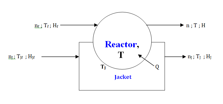
In this case the jacket equation is:
nJ.(HJf – HJ) - Q = 0.0 nJ.(HJf – HJ) = Q = ah .U.(TJ – T)
When there is no change of phase in the jacket/coil, we get, nJ. CPJ. (TJf - TJ) = Q = ah. U. (TJ – T) This equation will have to be solved simultaneously with the reactor equations. One extra state variable TJ and one extra equation, no change in the degrees of freedom.
Distributed jacket/coil
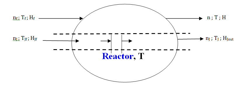
In this case the jacket equation is:
$$ n _ {J}. H _ {J} = Q ^ {\prime}. \Delta l + n _ {J}. \left(H _ {J} + \Delta H _ {J}\right) \rightarrow n _ {J}. \frac {d H _ {J}}{d l} = - Q ^ {\prime} $$ ’ ’ . . . ( ) .
when there is no change in phase, then the equation becomes; nJ . CpJ . dTJ / dl = -Q’ = -ah’ . U.(TJ – T) where, ah’ = heat transfer area per unit length and the initial condition of the differential equation is, at l=0.0, TJ = TJf , and T the temperature of the reactor is a constant, because the reactor is CSTR.
Tubular Reactors
This case of course belongs to the distributed system type, where both balances must be developed over a differential element.
Mass Balance Design Equation
j ij t i r A dl dn
N ∑ / σ = =
j
1 For a single reactions the above equation become, i t i σ = or /r dV dn /r A dl dn i i σ = ) ( Q H r A dl dH n t M $$ \sum_ {i = 1} ^ {M} n _ {i} \frac {d H _ {i}}{d l} = A _ {t} r ^ {\prime} (- \Delta H) + g $$ / / =
1 i For multiple reactions it will be:
$$ \sum_ {i = 1} ^ {M} n _ {i} \frac {d H _ {i}}{d l} = \left(\sum_ {i = 1} ^ {N} A _ {t} r _ {j} ^ {\prime} (- \Delta H\right) $$ ) ( Q H r A dl dH n j j N t i M i + / / = =
1 1 j i The above material and enthalpy balance design equations must be solved simultaneously to design the non-isothermal Tubular Reactor. A. Adiabatic:
For the adiabatic case we simply put, Q’ = 0.0 B. Non-Adiabatic:
$$ Q ^ {\prime} = a _ {h} ^ {\prime}. U. \left(T _ {J} - T\right) $$
Constant Jacket/Coil Temperature
= −Δ + ∑ ∑
M N i i t j j i j
dH n A r H dl = =
/ ' ( ) a .h . U.( T - T)
J 1 1
Where TJ is a constant
Varying Jacket/Coil Temperature
$$n_J. H_J = Q'. \Delta l + n_J. (H_J + \Delta H_J) \rightarrow n_J. dH_J / dl = -Q'$$
when there is no change in phase, then the equation becomes;
$$n_J. C_{pJ}. \frac{dT_J}{dl} = -Q' = -a_h'. U. (T_J - T)$$
Batch Reactors
Mass Balance Design Equation
Taking the limit as $\Delta t \to 0$ and rearranging gives,
$$\frac{dn_i}{dt} = V \sum_{j=1}^{N} \sigma_{ij} r'_j$$
For single reaction it will be,
$$\frac{dn_i}{dt} = V \sigma_i r'$$
Enthalpy Balance Design Equation
The above equation can be rearranged and written as,
$$\sum_{i=1}^{M} n_i \frac{dH_i}{dt} = V r' (-\Delta H) + Q'$$
For multiple reactions it becomes,
$$\sum_{i=1}^{M} n_i \frac{dH_i}{dt} = \left( V \sum_{j=1}^{N} r'_j (-\Delta H_j) \right) + Q'$$
The above material and enthalpy balance design equations must be solved simultaneously to design the non-isothermal Tubular Reactor.
A. Adiabatic:
For the adiabatic case we simply put, $Q' = 0.0$
B. Non-Adiabatic:
$$Q' = a_h'. U. (T_J - T)$$
Constant Jacket/Coil Temperature
$$\sum_{i=1}^{M} n_i \frac{dH_i}{dt} = \left( \sum_{j=1}^{N} V. r'_j (-\Delta H_j) \right) + a_h'. U. (T_J - T)$$
Where $T_J$ is a constant
Varying Jacket/Coil Temperature
More difficult, because if there is variation in space it will give Partial Differential Equations (PDEs). If it is only varying in time and we can consider the jacket/coil lumped, then the heat balance for the jacket will be (for batch heating),
$$\bar{n}_J \frac{d\bar{H}_J}{dt} = -a_h'. U. (T_J - T)$$
for perfectly mixed coil/jacket, but with continuous input/output
$$\bar{n}_J \frac{d\bar{H}_J}{dt} + n_J. H_J - n_{jf}. H_{jf} = -a_h'. U. (T_J - T)$$
Either of the above equations (depending on the design of the cooling jacket/coil) will need to be solved simultaneously with the batch reactor equations.
Conclusion
This short communication provides a systematic approach for the formulation of design, simulation, optimization and control equations suitable for different types of reactors in the petroleum industry. It shows this systematic approach and how it can be applied for different types of reactors and inform the reader about the different techniques for the numerical solution of the model equations for different types of reactors and also inform the reader about the source of the methodology used which is based on System Theory (ST) [1].
References
-
Elnashaie SSEH, Garhyan P (2003) Conservation Equations and Modeling of Chemical and Biochemical Processes. Dekker M, New York, USA, pp: 636.
- Nigeria’s Vulnerability in the Face of Global Energy Policy
- A Simulation Study of Investigation of Optimum Oil Production Performance by Applying Various Gas Injection Methods in Oil Reservoir
- Characterization of Permo-Triassic Reservoirs through Thermal Maturity Assessment of Westphalian Source Rocks in the Cheshire Basin
- Influence of Microwax on the Rheological and Thermal Behaviour of a Wax Crude Oil
- Real-Time Monitoring and Performance Optimization of Steam Injection in Heavy Oil Reservoirs Using Fiber Optic Sensing and Integrated Predictive Simulation Models
- Rapid On-Site Determination of the Total Petroleum Hydrocarbon Content of Soils by Handheld Fourier Transform Near-Infrared Spectroscopy: Development of a Global, Site- and Scanner- Independent Calibration Model