Calculation and Comparison of Parameters during Fire in Large Capacity Crude Oil Storage Tanks
The heat release rate during a fire is an initial parameter for calculating average flame height. Average flame height is essential for subsequent calculations of heat flow density and also for setting separation distances. The article calculates and compares the values of these two basic parameters in a fire in three real, existing large-capacity tanks for the storage of crude oil. The stated calculations are for the two most difficult scenarios of five possible fire scenarios for above ground double-walled storage tanks with floating roofs. The calculations showed that increasing the diameter of the tank increases the flame height, but not in proportion, and above a certain threshold diameter of the tank remains virtually constant.
Horváth J1, Kačík F1,2* and Danihelová A1
Prague, Kamýcká 1176, Praha 6 - Suchdol, 16521 Czech Republic, Email: kacik@tuzvo.sk constant.
Keywords: Storage tank; Oil fire; Fire parameters; Heat release rate; Average flame height
Introduction
Ignitable liquids pose challenging problems for fire protection because they can readily initiate combustion, burn with high heat release rate (HRR), spread the flame rapidly, and are difficult to extinguish [1]. In the world, there are currently several types of large-capacity storage tanks for crude oil. Oil is stored in underground large- capacity bunkers or above ground in large-capacity containers and tanks. Individual liquefied gas petroleum or liquid petroleum products are stored similarly. In terms of their overall design and location we can divide large capacity over ground tanks into:
- single wall steel tanks protected around the perimeter by an earth wall,
- two or more single wall steel tanks protected by an earth wall,
- single wall steel tanks protected by a reinforced concrete perimeter wall,
4. reinforced concrete tanks, 5. double wall storage tanks, 6. double wall storage tanks protected by an earth wall, 7. two or more wall storage tanks protected by an earth wall. Depending on the type of roof we can divide large capacity tanks into:
- open – without roof,
- tank with a fixed roof,
- tank with a floating roof [2].
Double wall large-capacity tanks in above-ground designs are of a vertical, cylindrical shape, welded from steel components, all-metal. They have a chamber-floating roof that floats on the surface of the stored liquid. The roof is also made from welded steel components. The air chambers created enable the roof to float on the surface of the stored liquids. In the case of crude oil ignition, the rapid spread of fire and intense combustion can be expected. The fire spreads across the surface of the flammable liquid over its whole area. Oil has a high calorific value and flame temperature in which fire reaches up to 1,400°C [3].
Iwata in testing 14 kinds of oil in a conical calorimeter we found a correlation between HRR and density, whereby at a higher density of oil, HRR fell [4]. The flame height ($L_f$) depended on the cylindrical diameter ($D$) and the ratio of $L_f/D$ decreases with increasing the diameter of the tank [5]. Large-scale pool fires have been studied in great detail for several decades. The extensive work on hydrocarbon based fuels is based on a number of large scale tests including fuels like gasoline, crude oil, kerosene and ethanol [5, 6, 7, 8, 9, 10].
A series of well-defined parameters have been established to classify pool fires in a quantitative manner. Despite the enormous body of work on large-scale pool fires there are still significant uncertainties in our understanding of such fires and capabilities to predict their behaviour. There is a critical need for more well-instrumented experimental studies, as well as further development and validation of detailed numerical models. In fire protection engineering, there is a need to extend models for predictions of fire behaviour to large scale fire scenarios [11, 12].
The aim of the paper was therefore to calculate and compare the heat release rate and the height of flame in a fire in selected large-capacity tanks for storing crude oil.
**Experimental Part**
**Methodology of Calculation**
Calculation of parameters in a fire was undertaken for selected sizes of large-capacity tanks, which are currently in operation in Slovakia and the Czech Republic. The selected tanks by design and build are very similar. However, during the work, we focused on the impact of their different dimensions of heat release rate of fire and average flame height.
Fire Scenarios: In double wall above-ground storage tanks, where between the containment and storage tanks there is an area to capture the total amount of oil storage (interstice) it is necessary to consider several possible scenarios of fire:
- Fire in the space between the roof of the tank and the wall of the tank – scenario S1
- Fire in the containment tank and the space between the roof and the wall of the tank – scenario S2
- Fire in the storage tank – whole area (in the event of the floating tank roof sinking) – scenario S3
- Fire in the tank and containment tank (sunken roof of the storage tank and damaged wall of the storage tank) S4
- Fire in the containment tank (interstitial fire) S5
A damaged storage tank is the most difficult scenario in which fire affects the entire total area of the interstice and the area of the storage tank. For simplification, the horizontal surface is calculated using the diameter of the emergency tank, which is the sum of the areas of the storage tank and the interstice. Baseline for our calculations and subsequent comparison will be Scenarios S3 and S4.
**Parameters during Fire**
Heat release rate during fire ($Q^*$):
Heat released per unit of time ($kJs^{-1}$), which changes with time.
- for a natural fire in the tanks the speed becomes constant,
- it depends on the diameter of the tank $D$,
- for a diameter above 0.2 m the rate of combustion by area increases with the diameter to a defined value, after which it is constant,
- it depends on the constant $k \times \beta$ the product of the radiation flow characteristic for the fuel (tabulated for liquids and thermoplasts).
In the case of crude oil combustion in large capacity tanks, we expect the fire to be governed by fuel, insofar as the access of air into the fire zone should not be limited in any way.
We calculate the heat release rate as:
$$Q^* = A_f \times m_\infty^* \times (1 - e^{-k \times \beta \times D}) \times \chi \times \Delta H_C$$ (1)
$A_f$- horizontal combustion area ($m^2$)
$m_\infty^*$- rate of combustion by area ($kgm^{-2}s^{-1}$), for crude oil = $(0.02833 \text{ kgm}^{-2}s^{-1})$
$k \times \beta$- product of constant radiation flow from the flame and the surface of the flammable liquid $(2.8 \text{ m}^{-1})$
$D$- diameter of tank ($m$)
$\chi$- efficiency of combustion ($\%$), for crude oil = (70 % i.e. 0.7)
$\Delta H_c$- total heat of combustion ($kJkg^{-1}$), for oil = $(42.5 \text{ MJkg}^{-1} = 42,500 \text{ kJkg}^{-1})$
Average height of flame ($L_f$):
Averaging the height of the luminous flame over time, $y$ (appearance of a flame) 1.0 stable flame, 0.5 in the middle of the time, at horizontal distance $L$ (m) from the flame is found experimentally from video recordings - conformance with subjective visual perceptions.
Correlation of flame height – the reason is the turbulent nature, dependence on the area of combustion D and heat release rate Q˙. We calculate the average height of flame [13]:
$$ L _ {f} = 0. 2 3 5 \times Q ^ {\frac {2}{5}} - 1. 0 2 \times D $$
$$ = 0. 2 3 5 \times Q ^ {5} - 1 $$
(2) Storage tank with a volume of 30,000 m3 (cross section and parameters are in (Figure 1)) – calculation:
![Figure 1: Cross section of tank with volume 30,000 m3. D – diameter of tank (42.8 m) Dh – diameter of containment tank (53.6 m) Af – horizontal combustion area of tank (1,439 m2) Af h – horizontal combustion area of containment tank (2,256 m2) " ∞ m – rate of combustion by area (0.02833 kgm-2s-1) k×β – product of constant radiation flow from the flame to the surface of the flammable liquid (2.8 m-1) χ – efficiency of combustion of crude oil (70 % i.e. 0.7) ΔHc – total heat of combustion of crude oil (42.5 MJkg-1 = 42,500 kJkg-1) Values used in the calculation were taken from literature [13].](/fulltextimages/1593/fig_1.png)
Figure 1: Cross section of tank with volume 30,000 m3. D – diameter of tank (42.8 m) Dh – diameter of containment tank (53.6 m) Af – horizontal combustion area of tank (1,439 m2) Af h – horizontal combustion area of containment tank (2,256 m2) " ∞ m – rate of combustion by area (0.02833 kgm-2s-1) k×β – product of constant radiation flow from the flame to the surface of the flammable liquid (2.8 m-1) χ – efficiency of combustion of crude oil (70 % i.e. 0.7) ΔHc – total heat of combustion of crude oil (42.5 MJkg-1 = 42,500 kJkg-1) Values used in the calculation were taken from literature [13].
$$ Q ^ {\bullet} = A _ {f} \times m _ {\infty} ^ {\prime \prime} \times \left(1 - e ^ {- k \times \beta \times D}\right) \times \chi \times \Delta H _ {C} \left(\mathrm {k J s} ^ {- 1}\right) $$ Q˙ = 1,439×0.02833 × (1 – e-2.8 × 42.8 ) × 0.7 × 42,500 = 1,212,814.4 kJs-1 = 1,212.8144 MW For fire in a large capacity tank with a volume of 30,000 m3 the heat release rate is approximately 1,213 MW. The average flame height during the fire Lf :
$$ L _ {f} = 0, 2 3 5 \times Q ^ {\frac {2}{5}} - 1, 0 2 \times D $$
$$ = 0, 2 3 5 \times Q ^ {5} - 1 $$
(m) Lf = 0.235 × 1,212,814.4 2/5 – 1.02 × 42.8 = 20.1 m The average flame height during the fire is approximately 20.1 m Storage tank with a volume of 70,000 m3 (Figure 2) – calculation:
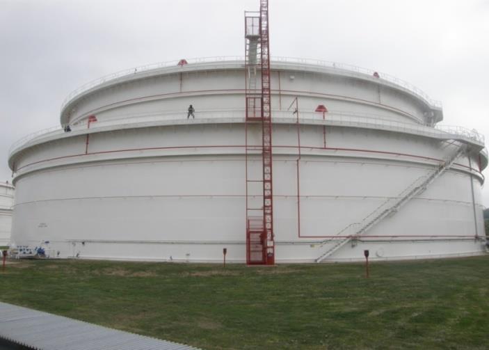
Figure 2: Storage tank with volume of 70,000 m3. D – diameter of tank (66 m) Dh – diameter of containment tank (80 m) Af – horizontal combustion area (3,421 m2) Af h – horizontal combustion area of containment tank (5,027 m2) m”∞ – rate of combustion by area (0.02833 kgm-2s-1) k× β – product of constant radiation flow from the flame to the surface of the flammable liquid (2.8 m-1) χ – efficiency of combustion of crude oil (70 % i.e. 0.7) ΔHc – total heat of combustion of crude oil (42.5 MJkg-1 = 42,500 kJkg-1) Q˙ = 3,421 × 0.02833 × (1 – e-2.8× 66) × 0.7 × 42,500 = 2,883,278.7 kJ/s = 2,883.2787 MW For fire in a large capacity tank with a volume of 70 000 m3 the heat release rate is approximately 2,883 MW. The average flame height during the fire Lf : Lf = 0.235 × 2,883,278.7 2/5 – 1.02 × 66 = 22.84 m The average flame height during the fire is approximately 22.84 m. Storage tank with a volume of 125,000 m3 (Figure 3) – calculation:
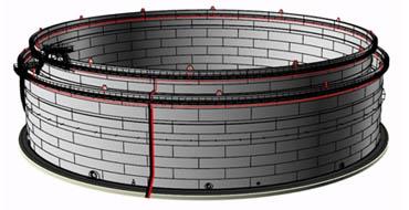
Figure 3: Depiction of storage tanks structure. D – diameter of tank (84.47 m) Dh – diameter of containment tank (90.47 m) Af – horizontal combustion area of tank (5,604 m2) Af h – horizontal combustion area of containment tank (6,428 m2) m”∞ – rate of combustion by area (0.02833 kgm-2s-1) k× β – product of constant radiation flow from the flame to the surface of the flammable liquid (2.8 m-1) χ – efficiency of combustion of crude oil (70 % i.e. 0.7) ΔHc – total heat of combustion of crude oil (42.5 MJkg-1 = 42,500 kJkg-1) Q˙ = 5,604 × 0.02833 × (1 – e-2.8 × 84.47) × 0.7 × 42,500 = 4,723,149.3 kJs-1 = 4,723.1493MW For fire in a large capacity tank with a volume of 125,000 m3 the heat release rate is approximately 4,723 MW. The average flame height during the fire Lf : Lf = 0.235 × 4,723,149.3 2/5 – 1.02 × 84.47 = 23.68 m The average flame height during the fire is approximately 23.68 m.
Results and Discussion
Table 1 shows the theoretical volume of the tank as well as real calculated volumes from the known dimensions of the tank and the maximum storage level of the oil. For each scenario (S3 and S4), the heat release rate during the fire and flame height of the flame during the fire is also stated. These parameters are compared in selected large-capacity tanks.
| Storage tank volume (m3) | 30,000 | 70,000 | 125,000 | |||
|---|---|---|---|---|---|---|
| Calculated storage tank volume (m3) | 29,062 | 72,803 | 124,968 | |||
| Scenario | S3 | S4 | S3 | S4 | S3 | S4 |
| Diameter (m) | 42.8 | 53.6 | 66 | 80 | 84.47 | 90.47 |
| Area (m2) | 1,439 | 2,256 | 3,421 | 5,027 | 5,604 | 6,428 |
| Q˙ (MW) | 1,213 | 1,901 | 2,883 | 4,237 | 4,723 | 5,418 |
| Lf (m) | 20.1 | 21.65 | 22.84 | 23.57 | 23.68 | 23.76 |
Table 1: Comparison of calculated parameters for selected scenarios. From the compared values for heat release rate during a fire
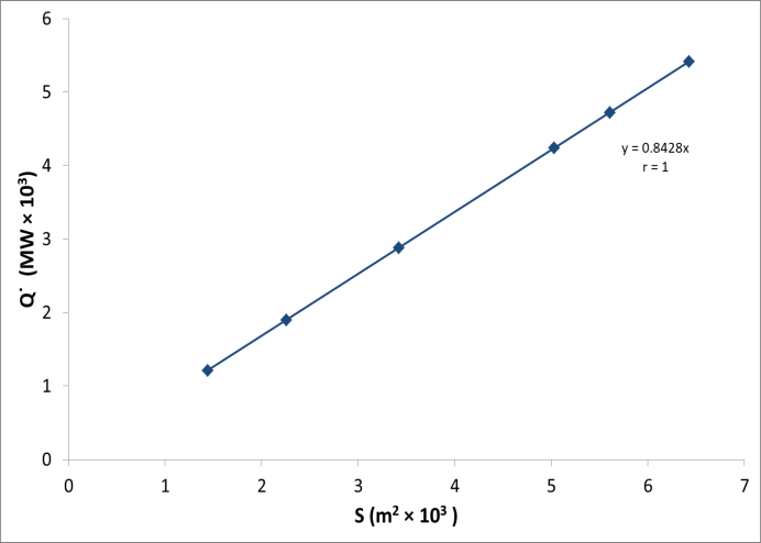
In the case of a fire in selected large-capacity tanks, we used the total horizontal surface of oil stored as the area of the fire. We found, for three selected tanks under two scenarios, the heat release rate was constant in terms of energy per unit of time per unit area with a value of " f q = kWm-2 (0.8428 MWm-2) for oil with the stated characteristics. Baum and McGrattan report for a large storage tank of oil (with a mean of 84 m and height 27 m) the heat release rate during the fire is 4.7 GW, which when converted to a heat release rate per area comes to approximately " f q = kWm-2 (0.848 MWm-2), which corresponds well with our results [14]. With wind of 6 ms-
1 (at a height of 27 m above ground) an outside temperature of 20°C, they state the rate of energy release by area during a fire in the oil tank as " f q = 1,000 kWm-2 (1 MWm-2). After deducting the shielding of the flame by smoke during the crude oil fire, (we assume 10% shielding), the rate of release of energy by area " f q = 900
kWm-2 (0.9 MWm-2). McGrattan gives, for crude oil, a rate of energy release by area of " f q = 1,900 kWm-2, whereby they assume a rate of combustion by area for crude oil of m”∞ = 0.045 kgm-2s-1, with a total heat of combustion of ΔHc = 42,600 kJkg-1 and efficiency of combustion of χ = 1 (100 %) [15]. In the paper we assumed a combustion rate per area of m”∞ = 0.028 kgm-2s-1, with a total heat of combustion of ΔHc = 42,500 kJkg-1 and effectiveness of combustion of χ = 0.7 (70 %). Considering that we assumed a significantly lower rate of combustion and efficiency of combustion, the heat release rate per area was lower than that of the state authors by 55%. In comparing the average flame height for a fire between tanks and scenarios, there are only differences in the order of several centimetres to decimetres. The larges difference (1.55 m) is between the scenarios with a 30,000 m3 capacity tank, the smallest difference (8 cm) is seen between the scenarios with a 125,000 m3 capacity tank. Figure 5 shows that enlarging increases flame height, but not in direct proportion above a certain threshold of tank diameter (in our case approximately 80 metres) it remains practically constant.
![Figure 5: Dependence of flame height during a crude oil fire in a tank on its diameter. With a natural fire in tanks, the heat release rate during a fire becomes a constant, for a diameter over 0.2 m, the combustion rate by area increases with the diameter to the stated value, after which it is constant m” ∞ [13,16]. The values of m∞ and k′ were obtained for diesel oil and gasoline by various authors [17,18]. This allowed prediction of the burning rate as a function of pool diameter; the agreement between the calculated values and the experimental results was quite good.](/fulltextimages/1593/fig_5.png)
Figure 5: Dependence of flame height during a crude oil fire in a tank on its diameter. With a natural fire in tanks, the heat release rate during a fire becomes a constant, for a diameter over 0.2 m, the combustion rate by area increases with the diameter to the stated value, after which it is constant m” ∞ [13, 16]. The values of m∞ and k′ were obtained for diesel oil and gasoline by various authors [17, 18]. This allowed prediction of the burning rate as a function of pool diameter; the agreement between the calculated values and the experimental results was quite good.
Conclusions
Parameters were calculated for a fire in three different dimensions of tanks in the most difficult selected scenarios. Generally, it would suffice for large capacity tanks from a certain diameter to calculate using a constant heat release rate during a fire per unit time per unit area of oil storage with the same characteristics. Also, for other flammable liquids there should be a constant release of energy per unit time per unit area proportional to the total combustion heat, rate of combustion by area, combustion efficiency and the constant product of radiation flow from flame to the surface of the flammable liquid. In the calculated values, an average flame height was found considering the relation between the diameter and volume of the selected tanks to deviate from a few centimetres to tens of decimetres. For each tank, the average flame height was over 20 m. These values may be calculated only without wind, the effect of wind and other unexpected situations such squirting, boiling, deformation of tanks, or breach of the floating roof could increase flame height several-fold.
Acknowledgement
This work was supported by the Slovak Research and Development Agency under the contract No. APVV-16- 0326 (50%), and under the contract No. APVV-14-0468 “Development of an auxiliary device and its technological employment to increase the efficiency of extinguishing forest fires“(50%).
References
-
Yu HZ (2016) Investigation of Fire Extinguishment in Large Facilities based on Physical Scaling, Modeling and Testing. Fire Technology 52(6): 2143-2157.
-
Sharovarnikov AF, Molchanov VP, Voevoda SS, Sharovarnikov SA (2002) Extinguishing fires of oil and oil products. Moscow, pp: 448.
-
Koseki H (2000) Large scale pool fires: results of recent experiments. Fire Safety Science, Proceedings of the Sixth International Symposium, pp: 115-132.
-
Iwata Y, Koseki H, Janssens ML, Takahashi T (2001) Combustion characteristics of crude oils. Fire Materials 25(1): 1-7.
-
Koseki H, Iwata Y, Natsume Y, Takahashi T, Hirano T (2000) Tomakomai large scale crude oil fire experiments. Fire Technology 36(1): 24-38.
-
Koseki H, Yumoto T (1988) Air entrainment and thermal radiation from heptane pool fires. Fire Technology 24(1): 33-47.
-
Koseki H (1989) Combustion properties of large liquid pool fires. Fire Technology 25(3): 241-255.
-
Farahani HF, Shi X, Simeoni A, Ali SR (2015) A study on burning of crude oil in ice cavities. Proceedings of the Combustion Institute 35(3): 2699-2706.
-
Shi X, Bellino PW, Simeoni A, Rangwala AS (2016) Experimental study of burning behavior of large-scale crude oil fires in ice cavities. Fire Safety Journal 79: 91-99.
-
Sjöström J, Amon F, Appel G, Persson H (2015) Thermal exposure from large scale ethanol fuel pool fires. Fire Safety Journal 78: 229-237.
-
Steinhaus T, Welch S, Carvel RO, Torero JL (2007) Large-scale pool fires. Thermal Science 11(2): 101– 118.
-
Hu L (2017) A review of physics and correlations of pool fire behaviour in wind and future challenges. Fire Safety Journal 91: 41-55.
-
Karlsson B, Quintiere J (2000) Enclosure fire dynamics. CRC Press, New York, Washington, D.C, pp: 317.
-
Baum HR, McGrattan KB (1998) Simulation of large industrial outdoor fires. Fire Safety Science, pp: 611- 622.
-
McGrattan KB, Baum HR, Hamins AP (2000) Thermal Radiation from Large Pool Fires. National Institute of Standards and Technology, pp: 1-35.
-
Drysdale D (2011) An introduction to fire dynamics. 3rd (Edn.), John Wiley & Sons, pp: 512.
-
Chatris JM (2001) Experimental study of burning rate in hydrocarbon pool fires. Fuel and Energy Abstracts 43(4): 277.
-
Koseki H, Mulholland GW (1991) The effect of diameter on the burning of crude oil pool fires. Fire Technology 27(1): 54-65.
- Nigeria’s Vulnerability in the Face of Global Energy Policy
- A Simulation Study of Investigation of Optimum Oil Production Performance by Applying Various Gas Injection Methods in Oil Reservoir
- Characterization of Permo-Triassic Reservoirs through Thermal Maturity Assessment of Westphalian Source Rocks in the Cheshire Basin
- Influence of Microwax on the Rheological and Thermal Behaviour of a Wax Crude Oil
- Real-Time Monitoring and Performance Optimization of Steam Injection in Heavy Oil Reservoirs Using Fiber Optic Sensing and Integrated Predictive Simulation Models
- Rapid On-Site Determination of the Total Petroleum Hydrocarbon Content of Soils by Handheld Fourier Transform Near-Infrared Spectroscopy: Development of a Global, Site- and Scanner- Independent Calibration Model