Retrofit of Refinery Utility System by Total Site Heat Recovery: Practical Arrangements
This paper presents an optimisation of heat recovery of refinery site, a setting of utility targets of heating and cooling and indirect heat transfer between industrial clusters. The methodology provides the minimisation of capital cost of utility system retrofit. The optimisation of cost parameters connected with the heat transfer area of steam boilers and heaters, intermediate utility levels and a number of units. A method for calculation of a heat transfer area of intermediate utility heat exchangers is proposed. Minimum temperature approach of Total Site heat recovery is analysed and the number of steam mains, indirect heating loops, heat transfer area of boilers and condensers is calculated. The utility consumption, numbers of required units and material of equipment are analysed to optimise the retrofit investments. The case study shows optimal heat recovery of the refinery site of 1.94 MW. It reduces the consumption of middle-pressure steam by 37.3%, the cooling heat capacity is lowered by 39.6%. The investments of a retrofit project are paid back in 11.96 months.
Introduction
The refineries consume the one of largest share of delivered energy amongst all the sectors. a Despite lot of researches and developments of energy efficiency the oil refinery still has a huge potential for reducing energy consumption [1]. The role of energy in industry has become very important than ever due to environmental and economic reasons [2]. This issue has been prioritised due to a new EC goal of energy efficiency that has to be achieved till 2030; it should be improved by 27% [3]. Utility systems of oil refinery may contribute to energy efficiency and utilise of low potential heat across plant facilities as well as intersectional collaboration between utility company, refinery and residential sector [4]. These three part of energy consumers are connected and can be integrated to efficient use of primary energy sources. Total Site integration approach has demonstrated a potential of utility reduction [5], an optimisation of a cogeneration potential [6] and the use of different energy sources [7] including renewables [8].
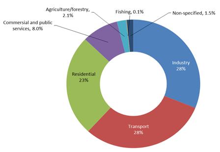
The energy efficiency improvement is one of the key goals sustainable of development in future. As
reported by IEA [9] the industrial energy consumption in 2012 was 28% of overall world energy balance (Figure1). A lot of energy efficiency approaches are based on Pinch Analysis, Mathematical Programming and Life Cycle Assessment as well as combinations and modifications of these methods as reported in 10. Klemeš JJ, et al. [10]. Čuček L, et al. proposed the multi-period synthesis of an optimally integrated regional biomass and bioenergy supply network through a mixed-integer linear programing (MILP) approach [11]. They obtained solutions with optimal selection of raw materials, technologies, intermediate and final product flows, and reduced greenhouse-gas emissions. In Čuček L, [12] presented combination of mathematical programming and life cycle assessment for biomass and bioenergy supply chain. In work [13] the authors delivered the application of Pinch Analysis for chemical plant and shown the reduction of energy consumption on 45%. Besides retrofit studies at site levels, there were several retrofits analysis performed at process level such as heat integration of sodium hypophosphite production [14], refinery [15], bromine production [13], cement production [16], milk powder production [17], cheese production [18], benzene production [19], coke-to- chemicals [20], biofuel production [21] etc.
Last time a big progress in energy efficiency of refinery processes was delivered accounting fouling problem [22], economic constraints [23] and more attention should be paid to site level. Firstly, it allows decreasing the energy consumption of industrial regions and reducing harmful emission considerably; secondly, it provides the possibility to utilise the industrial waste heat for energy needs of residential and commercial sectors that are a potential clients [24]. From the other side, it makes an appropriate background to implement an alternative energy sources including renewables that leads to additional reduction of energy prices and improves the environmental impact. The Total Site Analysis (TSA) is an approach that provides the utilisation of the waste industrial heat for different needs [25]. This direction is prioritised in different research labs due to wide application and a lot of approaches were developed last decade. Site energy improvements were proposed in Karimkashi S [26] that are based on the developments and modifications of the R-curve concept, which were previously developed by Kimura H and Zhu XX [27]. It was also used in [28] to estimate the investments of Total Site power cogeneration.
The authors in Nemet A, et al. [29] proposed using the intermediate utility loop to heat recovery of waste heat for energy needs inside the industrial clusters. This approach was later updated by Boldyryev S [30] and a methodology for minimisation of heat transfer area of steam boilers and condensers was provided. However, despite many successful industrial retrofit studies, there still remained several issues that remain unresolved and are of vital importance for the refineries, such as practical arrangements including plant layout, pressure drop, steam mains, number of steam boilers, steam traps etc. In this paper provides scientific approach and practical arrangements of retrofit of site utility system. There are recommendations for both engineers and plant managers to get technical details and decision making tools for economically viable retrofit of plant utility system.
Methods
It is possible to reduce the heat transfer area when implementing heat recovery of internal utility use. It was approved by Boldyryev S [30] and it depends on a certain temperature of intermediate utility loops. However, there are some technical issues of retrofit that contribute to capital investments such as numbers of heat transfer equipment as reported by Ahmad S, et al. [31], specific temperature difference, utility targets, recovery loops and energy prices [32]. Basically, the methodology grounded on basic principles of Pinch-point analysis [33] that is modified to use at Total Site level.
The developed approach consist of next stages: 1) Process Integration at individual units, energy targeting and utility requirements; 2) Total Site Profiles definition; 3) putting initial Total Site ΔTmin; 4) selection of enthalpy intervals, heat recovery and utility accounting all kinks of Copyright© Boldyryev S.
Boldyryev S. Retrofit of Refinery Utility System by Total Site Heat Recovery: Practical Arrangements. Pet Petro Chem Eng J 2018, 2(3): 000170.
Total Site Profiles; 5) putting of lower and upper bounds of intermediate utility loops for each enthalpy intervals; 6) calculation of heat transfer area of steam boilers and condensers in each enthalpy interval applying different temperature of steam mains; 7) optimising the level of steam mains determining minimum heat transfer of boilers and condensers; 8) calculation of numbers of boilers and condensers in all enthalpy intervals; 9) calculation of external utilities; 10) calculation of reduced investment and operation cost of retrofit; 11) applying previous steps for range of Total Site ΔTmin. The described procedure is illustrated in Figure 2.
![Figure 2: Total cost alternatives for Total Site heat integration (developed after [30]).](/fulltextimages/2701/fig_2.jpeg)
The heat transfer area of steam boilers and condensers for Total Site heat recovery loops and site utility units is calculated by (Equation 1):
$$ A _ {T o t a l} = A _ {T S H R} + A _ {T S H U} + A _ {T S C U} \tag {1} $$
The heat transfer area for hot and cold utility is calculated as reported in Smith R [33] selecting the utility temperature to minimise heat transfer area (Equation 2 and Equation 3).
1 𝑄𝑗 ℎ𝑗+
$$ \left. \Sigma_ {j = 1} ^ {m} \frac {Q _ {j}}{h _ {j}} + \frac {Q _ {H U}}{h _ {H U}}\right) _ {i} $$ $$ A _ {T S H U} = \sum_ {i = 1} ^ {l} \min _ {t 1 < t _ {H U} < t 2} \frac {1}{2} $$ $$ \sum_ {i = 1} ^ {l} \min _ {t 1 < t _ {H U} < t 2} \frac {1}{\Delta T _ {L M} ^ {C}} \left(\sum_ {j = 1} ^ {m} \frac {Q _ {j}}{h _ {j}} + \frac {Q _ {H U}}{h _ {H U}}\right) _ {i} (2) $$ 𝐶(∑ ∆𝑇𝐿𝑀 𝑖 𝐴𝑇𝑆𝐶𝑈= ∑ min 𝑡1<𝑡𝐶𝑈<𝑡2 1 𝐶(∑ 𝑄𝑖 ℎ𝑖+ 𝑄𝐶𝑈 ℎ𝐶𝑈 𝑛 𝑖=1 ) 𝑝 𝑗=1 (3) ∆𝑇𝐿𝑀 𝑗 Minimum heat transfer area on heat recovery loops is calculated by (Equation 4) that was previously modified in [Error! Reference source not found.]:
1 $$ \frac {1}{T _ {L M} ^ {H}} \left(\sum_ {i = 1} ^ {n} \frac {Q _ {i}}{h _ {i}} + \frac {Q}{h}\right) $$ 𝑄𝐼𝑀 ℎ𝐼𝑀 $$ A _ {T S H R} = \sum_ {z = 1} ^ {k} \min _ {t 1 < t _ {I M} < t 2} \left(\frac {1}{\Delta}\right) $$ $$ \sum_ {z = 1} ^ {k} \min _ {t 1 < t _ {I M} < t 2} \left(\frac {1}{\Delta T _ {L M} ^ {H}} \left(\sum_ {i = 1} ^ {n} \frac {Q _ {i}}{h _ {i}} + \frac {Q _ {I M}}{h _ {I M} ^ {H}}\right) + \right. $$ ∆𝑇𝐿𝑀 1 𝑄𝑗 ℎ𝑗+ 𝑄𝐼𝑀 ℎ𝐼𝑀 (4) $$ \left. \Sigma_ {j = 1} ^ {m} \frac {Q _ {j}}{h _ {j}} + \frac {Q _ {I M}}{h _ {I M} ^ {C}}\right) \Bigg) $$ 𝐶(∑ ∆𝑇𝐿𝑀 𝑧 The numbers of steam boilers, condensers and heat exchangers of external utility are calculated by Pinch- principles [33] assuming the number of units are the same as the number of streams in each enthalpy interval:
$$ \Sigma_ {i = 1} ^ {p} n _ {i} ^ {h} (5) $$
$$ \sum_ {i = 1} ^ {l} n _ {i} ^ {c}, $$
, 𝑁𝐶𝑈= ∑
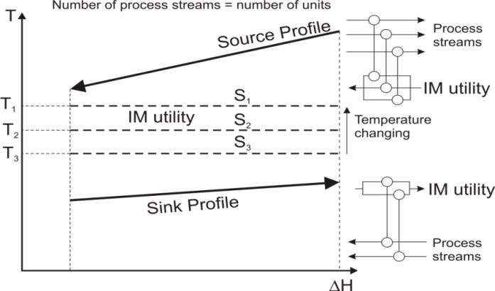
𝑛𝑖 𝑁𝐻𝑈= ∑ 𝑛𝑖 The number of heat exchangers of heat recovery loops is calculated from Sink and Source Profiles. There are arrays of heat boilers and condensers of intermediate utilities (Equation 6). It is based on the different intermediate utilities of recovery enthalpy intervals:
$$ \Sigma_ {i = 1} ^ {k} n _ {i} ^ {h} + n _ {i} ^ {c} (6) $$
ℎ+ 𝑛𝑖 𝑁𝐻𝑅= ∑ 𝑛𝑖
Total numbers of heat transfer units of site utility system are calculated from the Equation 7 and it is shown in Figure 3:
𝑁𝑇𝑜𝑡𝑎𝑙= 𝑁𝐻𝑅+ 𝑁𝐻𝑈+ 𝑁𝐶𝑈 (7)
Energy demands are calculated of range of Total Site ΔTmin from Total Site profiles [25]. The fuel consumption of site utility system may be calculated from energy demand, ambient temperature, temperature of flue gases, Copyright© Boldyryev S.
Boldyryev S. Retrofit of Refinery Utility System by Total Site Heat Recovery: Practical Arrangements. Pet Petro Chem Eng J 2018, 2(3): 000170.
and coefficient of excess air, furnaces and heaters efficiency. Cold utility consumption (e.g. cooling water, hot water, refrigerants etc.) is calculated based cold site energy targets, temperature differences and equipment efficiency.
The case study combined the stream data of 3 refinery units. These processes were integrated with use of Pinch- methodology. There are eight process streams available for Total Site integration and they are collected into the Table 1 with specific thermo-physical properties.
The investment costs of Total Site heat recovery are calculated from heat transfer area (Equation 1), numbers of steam boilers and condensers (Equation 7) and equipment price.
The Refinary Case Study
| Stream | Type | TS (°C) | TT (°C) | CP (MW/°C) | H (kW) | h (MW/(m2 C)) | ||||||||||||||
|---|---|---|---|---|---|---|---|---|---|---|---|---|---|---|---|---|---|---|---|---|
| Process A – 1 diesel | hot | 100 | 60 | 0.05 | 2 | 0.0007 | ||||||||||||||
| Process B – 1 feed gas mixture | hot | 180 | 130 | 0.03 | 1.5 | 0.0001 | ||||||||||||||
| Process C – 1 light fraction | hot | 80 | 40 | 0.02 | 0.8 | 0.0005 | ||||||||||||||
| Process D – 1 vacuum gasoil | hot | 145 | 85 | 0.01 | 0.6 | 0.0006 | ||||||||||||||
| Process A – 2 residue | cold | 70 | 120 | 0.03 | 1.5 | 0.0005 | ||||||||||||||
| Process B – 1 fuel oil | cold | 100 | 140 | 0.04 | 1.6 | 0.0009 | ||||||||||||||
| Process B – 2 product gas mixture | cold | 150 | 240 | 0.02 | 1.8 | 0.0002 | ||||||||||||||
| Process D – 2 fuel oil | cold | 130 | 160 | 0.01 | 0.3 | 0.0007 |
Table 1: Stream data for Site Profiles
Site hot utility is a middle pressure steam with saturation temperature 25°C that is supplied by boiler house, cold utility is cooling water with temperatures range in summer 28 to 35°C and ambient air. Film heat transfer coefficients for hot and cold utilities are 0.001 and 0.0079 MW/(m2 °C) respectively. The cost of hot utility is 366 EUR/kWy that corresponds to prices of natural gas in 2014 [34] and 10% conversion losses, the cost of cold utility is 36 EUR/kWy. The specific price of heat transfer area is taken of 800 Euro/m2. It is a price of plate heat exchangers with high corrosion resistance. The coefficient of nonlinearity of heat transfer area price is The super targets of Total Site were built and shown in Figure 4. It is plotted with use of data from Table 1 varying the minimum temperature approach of Total Site Profiles and temperature of intermediate utilities of enthalpy intervals. Minimum total cost is identified of 2,107,800 EUR and it is found at Total Site temperature approach of 31°C (Figure 4a-c).


0.87. Installation costs including revamp of 1 steam boiler or condenser are 10,000 Euro. The calculation is made for 5 years plant life and return on investment employed of 10%.

overlapping part of Total Site Profiles is representing the heat recovery. Sink and Source profile temperatures limit Copyright© Boldyryev S.
Boldyryev S. Retrofit of Refinery Utility System by Total Site Heat Recovery: Practical Arrangements. Pet Petro Chem Eng J 2018, 2(3): 000170.
- the low and upper bound of temperature range of intermediate utility loop. The utility pinches appear between Site Profiles and utility loops as presented in
- Enthalpy interval
- ΔH, MW
- TS, °C
- TT, °C
- ΔTmin, °C hIM1,
- MW/(m2∙°C)
- #1
- 0.3
- 83
- 93
- 8
- 0.00011
- 0.00012
- 786.16
- 2
- #2
- 0.6
- 110
- 110
- 10
- 0.008
- 0.0054
- 273.17
- 3
- #3
- 1.05
- 123
- 123
- 8
- 0.0079
- 0.0053
- 408.87
- 3
Table 2: Calculation results of heat recovery loops.
The realisation of retrofit of site utility system needs
| Hot utility (MW) | Cold utility (MW) | Recovery | Investment | Saving | Payback time | |||||||||
|---|---|---|---|---|---|---|---|---|---|---|---|---|---|---|
| (MW) | (EUR) | (EUR/year) | (months) | |||||||||||
| Base case | 5.2 | 4.9 | 0 | − | − | − | ||||||||
| Retrofit | 3.26 | 2.96 | 1.94 | 777,474 | 779,880 | 11.96 |
Table 3: Economic results of utility system retrofit.
Discussion
The current paper provides the application of site recovery system; it shows the real case study and provides a decision making tool for the plant managers of retrofit of refinery utility system. However, there are some things are still needed deeper discussion and investigation.
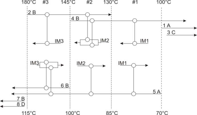
The heat exchangers network for Total Site heat recovery consists of multiple steam boilers, condensers, water heaters and coolers. This equipment proposed to be placed at appropriate steam mains but there is a Copyright© Boldyryev S.
Boldyryev S. Retrofit of Refinery Utility System by Total Site Heat Recovery: Practical Arrangements. Pet Petro Chem Eng J 2018, 2(3): 000170.
possibility for simplification of heat exchangers network and finding economic compromise between numbers of units, steam mains and heat transfer area. The number of heat exchangers and heat transfer area is higher comparison to individual processes due to heat transfer via intermediate utility loops. From the other hand the heat transfer coefficient of steam is much higher than of refinery process streams. In this case, the heat transfer area may be optimised with numbers of units, as mentioned above.
The trade-off of the heat recovery system is determined. Low price energy sources may move the retrofit project to the low heat recovery and bigger energy consumption. It decreases the realization time of retrofit project, which is very important for refinery operation schedule. The retrofit can be done during short time maintenance. The reduction of an energy prices may be done by renewables integration into site utility system but same measures have to be well analysed from scheduling point of view.
The additional analysis of site heat recovery systems should be delivered in the future work with the special attention to capital cost reduction by the selection of optimal level of intermediate utility loops and the simultaneous cogeneration opportunities. The design and revamp of site heat exchangers network deserves further attention. The summer operation mode should be analysed additionally because of heating and cooling demands will be changed and operation modes of boilers and condensers has to be adopted.
Conclusion
The presented paper minimises the retrofit cost of refinery utility system. It allows the practical recommendation of number of steam boilers and condensers as well as numbers steam mains, steam traps etc. The case study has shown a big potential of energy saving of refinery utility system. The use of excess heat provides a way to reduce the use of primary energy and to contribute to global CO2 mitigation. The heating demands may be reduced by 37.3% and cooling demands by 39.6%; it is needed capital investments of 777,474 Euro and retrofit is payed back in 11.96 months. The result of this work may be used for practical recommendation of retrofit of site utility systems as well for design of energy systems of industrial regions.
Acknowledgments
The financial support by the EC and Croatian Ministry of Science Education and Sports project “CARBEN” (NEWFELPRO Grant Agreement No. 39).
Nomenclature
T temperature, °C;
ΔH enthalpy, kW;
Atotal total heat transfer area, m2;
ATSHR minimum heat transfer area of heat recovery, m2;
ATSHU minimum heat transfer area of steam boilers, m2;
ATSCU minimum heat transfer area of condensers, m2;
Δtmin minimum temperature difference between two process streams, °C
ΔTmin1 minimum temperature difference of source side, °C
ΔTmin2 minimum temperature difference of sink side, °C logarithmic temperature difference of source side, °C H LM T Δ logarithmic temperature difference of sink side, °C t1 temperature low bound, °C;
C LM T Δ t2 temperature upper bound, °C;
Qi heat of i hot stream, kW;
Qj heat of j cold stream, kW;
QIM heat of intermediate utility of enthalpy interval, kW; QRECOVERY load of heat recovery, kW Copyright© Boldyryev S.
Boldyryev S. Retrofit of Refinery Utility System by Total Site Heat Recovery: Practical Arrangements. Pet Petro Chem Eng J 2018, 2(3): 000170.
QHU heat of hot utility in enthalpy interval, kW;
QCU heat of cold utility in enthalpy interval, kW;
QHmin hot utility target, kW;
QCmin cold utility target, kW;
hi film heat transfer coefficient of i process stream, W/(m2 °C);
hj film heat transfer coefficient of j process stream, W/(m2 °C);
film heat transfer coefficient for condensation of intermediate utility, W/(m2 °C);
𝐶
ℎ𝐼𝑀 𝐻 film heat transfer coefficient for boiling of intermediate utility, W/(m2 °C);
ℎ𝐼𝑀 hHU film heat transfer coefficient of hot utility, W/(m2 °C);
hCU film heat transfer coefficient of cold utility, W/(m2 °C);
hIM1 film heat transfer coefficient of intermediate utility on source side, W/(m2 °C);
hIM2 film heat transfer coefficient of intermediate utility on sink side, W/(m2 °C); n number of hot streams in enthalpy interval;
m number of cold streams in enthalpy interval;
k number of enthalpy intervals for heat recovery; l number of enthalpy intervals for hot utility;
p number of enthalpy intervals for cold utility;
NHU number of heat exchangers for hot utility;
NCU number of heat exchangers for cold utility;
NHR number of heat exchangers for heat recovery; Ntotal total number of heat exchangers;
IM1 intermediate utility 1;
IM2 intermediate utility 2;
IM3 intermediate utility 3;
ℎ number hot streams in enthalpy interval; 𝑛𝑖 𝑛𝑖 𝑐 number hot streams in enthalpy interval.
References
-
Klemes JJ (2013) Handbook of Process Integration (PI): Minimisation of energy and water use, waste and emissions. 1st (Edn.), Woodhead Publishing Limited, Cambridge, UK.
-
Harjunkoski I, Hadera H (2016) Industrial Tools and Needs. _In:_ Martín M (Ed.), Alternative Energy Sources and Technologies: Process Design and Operation. Springer International Publishing, Switzerland, pp: 415-438.
-
European Commission Climate Action.
-
Boldyryev S, Krajačić G, Duić N (2016) Cost Effective Heat Exchangers Network of Total Site Heat Integration. Chemical Engineering Transaction 52: 541-546.
-
Boldyryev S, Varbanov PS (2015) Low potential heat utilization of bromine plant via integration on process and Total Site levels. Energy 90(Part 1): 47-55.
-
Boldyryev S, Varbanov PS, Nemet A, Klemeš JJ, Kapustenko P (2013) Capital Cost Assessment for Total Site Power Cogeneration. Computer Aided Chemical Engineering 32: 361-366.
-
Varbanov P, Perry S, Makwana Y, Zhu XX, Smith R (2004) Top-level Analysis of Site Utility Systems. Chemical Engineering Research and Design 82(6): 784-795.
-
Barkaoui A, Boldyryev S, Duic N, Krajacic G, Guzović Z (2016) Appropriate integration of geothermal energy sources by Pinch approach: Case study of Croatia. Applied Energy 184: 1343-1349.
-
IEA (International Energy Agency).
-
Klemeš JJ, Varbanov PS, Liew PY, Čuček L, Kravanja Z, et al. (2014) Recent developments in advanced process integration: Learning the lessons from industrial implementations. Applied Mechanics and Materials 625: 454-457.
-
Čuček L, Martín M, Grossmann IE, Kravanja Z (2014) Multi-period synthesis of optimally integrated biomass and bioenergy supply network. Computers & Chemical Engineering 66: 57-70.
-
Čuček L, Varbanov PS, Klemeš JJ, Kravanja Z (2012) Document Total footprints-based multi-criteria optimisation of regional biomass energy supply chains. Energy 44(1): 135-145.
-
Boldyryev S, Varbanov PS (2014) Process Integration for Bromine Plant. Chemical Engineering Transaction 39: 1423-1428. Copyright© Boldyryev S. Boldyryev S. Retrofit of Refinery Utility System by Total Site Heat Recovery: Practical Arrangements. Pet Petro Chem Eng J 2018, 2(3): 000170.
-
Tovazhnyansky L, Kapustenko P, Ulyev L, Boldyryev S, Arsenyeva O (2010) Process integration of sodium hypophosphite production. Applied Thermal Engineering 30(16): 2306-2314.
-
Tovazhnyanskii LL, Kapustenko PA, Ul’ev LM, Boldyrev SA, Arsen’eva OP (2009) Thermal Process Integration in the AVDU A12/2 Crude Distillation Unit during Winter Operation. Theoretical Foundations of Chemical Engineering 43(6): 906-917.
-
Boldyryev S, Mikulčić H, Mohorović Z, Vujanović, M, Krajačić G (2016) The improved heat integration of cement production under limited process conditions: A case study for Croatia. Applied Thermal Engineering 105: 839-848.
-
Walmsley TG, Walmsley MRW, Atkins MJ, Neale JR (2013) Improving energy recovery in milk powder production through soft data optimisation. Applied Thermal Engineering 61(1): 80-87.
-
Kapustenko PO, Ulyev LM, Boldyryev SA, Garev AO (2008) Integration of a heat pump into the heat supply system of a cheese production plant. Energy 33(6): 882-889.
-
Tovazhnyansky L, Kapustenko P, Ulyev L, Boldyryev S (2011)Heat Integration Improvement for Benzene Hydrocarbons Extraction from Coke-Oven Gas. Chemical Engineering Transaction 25: 153-158.
-
Ulyev LM, Kapustenko PA, Vasilyev MA, Boldyryev SA (2013) Total Site Integration for Coke Oven Plant. Chemical Engineering Transactions 35: 235-240.
-
Nagy E, Mizsey P, Hancsók J, Boldyryev S, Varbanov P (2015) Analysis of energy saving by combination of distillation and pervaporation for biofuel production. Chemical Engineering and Processing: Process Intensification 98: 86-94.
-
Vasilyev M, Boldyryev S (2018) Process integration accounting fouling in heat exchanger network: a case study of crude oil distillation retrofit. Chemical Engineering Transactions 70: 2149-2154.
-
Ulyev L, Vasiliev M, Boldyryev S (2018) Process integration of crude oil distillation with technological and economic restrictions. J Environ Manage 222: 454-464.
-
Hackl R, Andersson E, Harvey S (2011) Targeting for energy efficiency and improved energy collaboration between different companies using total site analysis (TSA). Energy 36(8): 4609-4615.
-
Klemes JJ, Dhole VR, Raissi K, Perry S, Puigjaner L (1997) Targeting and design methodology for reduction of fuel, power and CO2 on total sites. Applied Thermal Engineering 17(8-10): 993-1003.
-
Karimkashi S, Amidpour M (2012) Total site energy improvement using R-curve concept. Energy 40(1): 329-340.
-
Kimura H, Zhu XX (2000) R-Curve concept and its application for industrial energy management. Ind Eng Chem Res 39(7): 2315-2335.
-
Varbanov PS, Boldyryev S, Nemet A, Klemes JJ, Kapustenko P (2013) Targeting of the Trade-Off of Capital Cost and Carbon Footprint for CHP. Proceedings of the 6th International Conference on Process Systems Engineering (PSE ASIA), Kuala Lumpur, pp: 227-232.
-
Nemet A, Boldyryev S, Varbanov PS, Kapustenko P, Klemeš JJ (2012) Capital cost targeting of total site heat recovery. Chemical Engineering Transactions 29: pp. 1447-1452.
-
Boldyryev S, Varbanov PS, Nemet A, Klemeš JJ, Kapustenko P (2014) Minimum heat transfer area for Total Site heat recovery. Energy Conversion and Management 87: 1093-1097.
-
Ahmad S, Linnhoff B, Smith R (1990) Cost optimum heat exchanger networks-2. Targets and design for detailed capital cost models. Comput Chem Eng 14(7): 751-767.
-
Klemeš JJ, Varbanov PS, Wan Alwi SR, Manan ZA (2014) Process Integration and Intensification Saving Energy, Water and Resources. De Gruyter.
-
Smith R (2016) Chemical Process Design and Integration. 2nd(Edn.), John Wiley & Sons, Chichester, UK.
-
Eurostat, Electricity and natural gas price statistics. Copyright© Boldyryev S. Boldyryev S. Retrofit of Refinery Utility System by Total Site Heat Recovery: Practical Arrangements. Pet Petro Chem Eng J 2018, 2(3): 000170.
- Nigeria’s Vulnerability in the Face of Global Energy Policy
- A Simulation Study of Investigation of Optimum Oil Production Performance by Applying Various Gas Injection Methods in Oil Reservoir
- Characterization of Permo-Triassic Reservoirs through Thermal Maturity Assessment of Westphalian Source Rocks in the Cheshire Basin
- Influence of Microwax on the Rheological and Thermal Behaviour of a Wax Crude Oil
- Real-Time Monitoring and Performance Optimization of Steam Injection in Heavy Oil Reservoirs Using Fiber Optic Sensing and Integrated Predictive Simulation Models
- Rapid On-Site Determination of the Total Petroleum Hydrocarbon Content of Soils by Handheld Fourier Transform Near-Infrared Spectroscopy: Development of a Global, Site- and Scanner- Independent Calibration Model