A Laboratory Investigation on the Way to Remove the Filter Cake Generated by Ilmenite Water-Based Drilling Fluids
The increasing demand for deeper drilling and more complicated wells fastens the way for improved drilling fluid (mud) technologies and promising additives. Several studies have shown numerous improvements in mud characteristics upon using ilmenite compared to the commonly used weighting materials. This study aims at investigating the removal of filter cake deposited by ilmenite water-based drilling fluid under harsh conditions using low-concentration (7.5 wt%) of hydrochloric acid (HCl) and chelating agent (HEDTA) to prevent iron precipitation during reaction. API filter press was used to conduct the filtration tests and generate the filter cake at a pressure ~ 300 psi and temperature ~ 250°F. Different sandstone cores of 2.5-in. diameter and 1-in. thickness were used to simulate the formation during filtration. Filtrate fluids were collected for 30 minutes as per API procedures and computerized tomography (CT) scan was used to characterize the cores with the deposited filter cakes. The filter cakes were soaked with HCl–chelate solution for six hours. Cores with the remaining filter cakes were CT scanned again. Effluent solutions resulting from the aforementioned soaking process were analyzed using inductively coupled plasma (ICP). Scanning electron microscopy–energy dispersive spectroscopy (SEM-EDS) was used to analyze the dried filter cakes and remaining residue. CT scan and SEM-EDS showed two layers of the filter cake with different densities but similar elemental composition. Using 7.5 wt% of HCl can partially remove the filter cake generated by ilmenite water-based drilling fluids. Adding the chelate showed minimal impact on the filter cake removal-efficiency; however, it helped nullify the corrosion issues during the treatment. This study provides a step forward on the way to chemically remove ilmenite-based filter cake using low acid concentration and virtually overcome corrosion issues encountered while acidizing.
Introduction
The petroleum industry nowadays is facing new and difficult technical challenges to keep up with the growing global energy demand. Challenges are related to remote locations, harsh drilling conditions, and unconventional reservoirs that make conventional exploration and production methods not efficient [1]. Engineers mostly drill wells overbalance to prevent well kicks and blowouts. Weighting materials helps to increase the density of the drilling fluid and thus elevate the hydrostatic pressure in the well over that inside the formation. API-barite is the most commonly used weighting material [2]; however, it is not applicable in different conditions. When using high-density drilling fluid weighted with barite, rheological properties become challenging. In addition, the filter cake generated by barite facing several removal issues. Barite contains several heavy components including lead, cadmium, mercury, and arsenic, which can be potential sources of pollution. In addition, the supply of barite is geographically limited, increasing its transportation costs [3, 4]. Different iron-bearing weighting materials have been used in the oil and gas industry since the 1970s. Iron oxide [5, 6], and iron carbonate [7] have been laboratory tested. Bloomberg, et al. [3] investigated ilmenite (FeTiO3)-based drilling fluid and observed a flow-induced abrasion problem. Those researchers suggested reducing the particle size by removing large particles. In 2001, a semi-submersible offshore rig near northern Norway used ilmenite in the drilling fluid for weight control [8]. They further decreased the mean particle size of ilmenite from an average of 50 microns to 10 microns and got acceptable erosion rates, especially for water-based drilling fluid. The replacement of barite by ilmenite can alleviate many of the challenges in the field. It has fewer heavy metals than barite, and thus makes onshore treatment easier. Amighi and Shahbazi [9] recommended using ilmenite or manganese tetraoxide instead of barite for high pressure-high temperature (HP/HT) drilling operations and high-angle wells. Al-Bagoury and Steele [2] introduced a new micronized ilmenite that can be used with both water- and oil-based muds under difficult drilling conditions and fluid requirements, which had an even smaller average particle size of 5 microns. Using this micronized ilmenite showed low plastic viscosity and low sag tendency compared to API-barite. These features are of great importance and can be employed in challenging drilling operations such as horizontal drilling, low margin pressure drop, deep water, and slimehole. The new grade of micronized ilmenite showed excellent dynamic sag, stable rheology and high acid solubility for both water- and oil-based applications [10, 11, 12, 13, 14, 15].
Recently, several studies showed successful field applications of drilling fluids weighted using ilmenite. Al-Bagoury [16] designed invert-emulsion mud using synthetic-based oils weighted with micronized ilmenite. These fluids show the ability of micronized ilmenite to provide significantly lower rheology to control equivalent circulation density (ECD), significantly reduced sag potential and lowered formation damage. Ivan, et al. [17] and Feder [18] discussed the history of drilling-fluids application in a reservoir drilling campaign offshore Abu Dhabi, from the early use of a solids-free, brine-/water-based mud to the application of nondamaging, nonaqueous fluids (NAFs) with micronized acid-soluble ilmenite. Using micronized, acid-soluble ilmenite lowered ECD as compared with sized calcium carbonate. Additionally, the evolution of breaker formulations allowed for longer breakthrough time, which allowed for better coverage of the lateral, better removal of the filter cake, and, ultimately, enhanced production through improved inflow profiles. A synthetic-based mud containing ilmenite yielded lower ECD when applied in South East Asia [19]. A field application of nondamaging oil-based mud (OBM) using micronized-ilmenite was presented by Ibrahim, et al. [20]. The new system showed lower plastic viscosity, higher drilling rate, lower friction factor which reduced torque and drag. A systematically evaluation was conducted for a potential weighting material to accomplish an ultra-high-density oil-based drilling fluid system (19.62 to 22.12 ppg) aimed to utilize in ultra-HP/HT conditions (>30000 psi and >410°F) [21, 22]. Results revealed that ultra-micro manganese and ilmenite complex after suitable surface treatment could act as an ideal weighting material than ultra-pure barite or other materials, which could fail in rheology and sag measurement with such high temperature and density. Moreira, et al. [23] discussed the best practices to mitigate risk, reduce complexity, and ensure improved drilling performance using slim hole to revitalize existing wells using re-entry drilling techniques in association with MRC (Maximum Reservoir Contact) and ERD (Extended Reach Drilling) designs. The best option of drilling fluid in this study was selected to be “Synthetic Organophilic Clay Free Invert Emulsion Fluid System”. This system was designed to cover lower mud weight range from as low as 8.5 ppg to as high as 12.8 ppg. For high weighted fluid, micronized ilmenite was used as a secondary weighting agent and reservoir friendly material to mitigate formation damage. It helps to maintain lower rheology, reduces sag risk, and it is less abrasive compared to barite and acid soluble systems (particles roundness is 80%).
Drilling fluids with new weighting materials, like ilmenite and manganese tetra-oxide, have unique advantages during the drilling process than using barite and cause little operational problem; however, filter cakes generated by those drilling fluids are hard to remove. Filter cake is generated during the drilling process on purpose to control the fluid invasion into the formation. Small particles, usually called bridging materials and most likely calcium carbonate, accumulate on the pores of the rock. As a consequence, fluid starts to build a thin layer on the surface of the wellbore. This thin and strong layer (filter cake) can prevent additional fluid from going into the formation, thus mitigating formation damage. After drilling, it is necessary to remove this layer to further damage control.
Ilmenite is mainly composed of FeTiO$_3$ and reacts with HCl, as follows [24]:
$$\text{FeTiO}_3 + 2\text{HCl} \rightarrow \text{Fe}^{2+} + \text{TiO}^{2+} + 2\text{Cl}^- + 2\text{OH}^-$$
The problem with the dissolution of ilmenite is iron, which can precipitate under acidic environments and cause formation damage. Smith, et al. [25] found iron (III) precipitation at a pH of 2. Taylor, et al. [26] showed that iron hydroxide can precipitate at a pH of 1 and the reaction was almost complete at a pH of 2 and room temperature. Precipitation will occur even earlier at higher temperatures.
By adding HCl, the filter cake can be dissolved but this causes iron precipitation. As for the removal of the ilmenite filter cake different work is done. In one study, HCl at a low concentration (5 wt%) was used to remove filter cake generated by ilmenite water-based drilling fluid [12]. Chelating agent and glycolic acid had also been tested individually. The conclusions drawn at that time were that neither chelate nor glycolic acid alone are effective in removing the filter cake generated by ilmenite water-based drilling fluid. Xiao, et al. [15] removed ilmenite filter cakes based on oil-based drilling fluid. To remove filter cake generated by oil-based mud, a mutual solvent was first used to change oil-wet filter cake to a water-wet one. Then similar procedures were followed. Those studies reported that higher concentration of HCl (10-15 wt%) should be used to remove the filter cake generated by ilmenite-weighted drilling fluid.
The objective of this work is to evaluate the effectiveness of using HCl at a lower concentration of 7.5 wt% to remove the filter cake generated by ilmenite water-based drilling fluids. In addition, 7.5 wt% HEDTA (hydroxyethyl ethylenediamine triacetic acid) as a chelant was also investigated to stabilize cations, especially iron, and prevent precipitation. HEDTA can react with cations that have two or three positive charges and form complexes, which are soluble in water. The results showed higher potential of the HCl– HEDTA solution to remove ilmenite water-based filter cakes. The filter cake characteristics were also investigated using different techniques to help in drawing comprehensive insights and conclusions. The study presented a trial on the way to chemically remove ilmenite-based filter cake using lower HCl concentration and virtually overcome corrosion problems.
Experimental Studies
Materials
Fully-formulated water-based drilling fluid was used in this research contained micronized ilmenite. The mud formulation consists of KOH, KCl, and defoamer, which were used as alkalinity control agent, shale inhibitor, and anti-foamer, respectively. Xanthan gum was used to provide primary viscosity, and modified starch to adjust the final rheological properties and fluid loss. Polyanionic cellulose (PAC-R) used as API filtrate loss additives. Besides, calcium carbonate (medium 50 µm and fine 25 µm) was used as bridging material. Finally, mirconized ilmenite (5 µm) was provided and used as a weighting material. All of the aforementioned additives were provided by different service companies and used as received. The particle size distribution of miconized ilmenite is shown in Table 1 as described by Ibrahim, et al. [20]. Ilmenite is a mixed metal oxide (FeTiO3) with a hydroxyl group on the surface, which yields different surface chemistries when compared to the most commonly used barite.
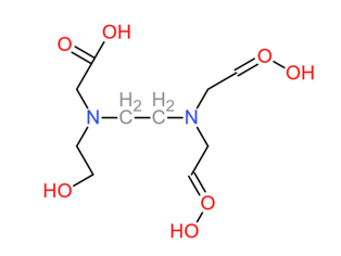
Hydruclaric acid (HCl) was provided from a chemical company with a concentration of 36.31 wt%. The chelate used was HEDTA (hydroxyethyl ethylenediamine triacetic acid) has a pH of 4 and a concentration of 42.5 wt%. Figure 1 shows the chemical structure of HEDTA. To simulate the formation during the filtration process, Berea and Bandera core disks were cut in dimensions of 2.5-in. diameter and 1.0-in. thickness from big core blocks. Tables 2 & 3 show the porosity and permeability of the cores used in this study and their mineral composition as revealed from X-ray diffraction (XRD), respectively.
| Parameter | d 10 | d 50 | d 90 | Density | Bet |
|---|---|---|---|---|---|
| Value | 2 µm | 5.5 µm | 12.2 µm | 4.6 g/cm3 | 1.5 m2/g |
Table 1: Particle size distribution of micronized ilmenite [20].
| Sandstone Core | Porosity (vol%) | Permeability (mD) | |
|---|---|---|---|
| Low-permeability Bandera sandstone | 10 | 6 | |
| High-permeability Bandera sandstone | 20 | 80 | |
| High-permeability Berea sandstone | 18 | 60 | |
| Berea Sandstone | Bandera Sandstone | ||
| Mineral | Concentration (wt%) | Mineral | Concentration (wt%) |
| Quartz | 91 | Quartz | 59 |
| Kaolinite | 3 | Kaolinite | 3 |
| Microline | 4 | Albite | 12 |
| Muscovite | 1 | Chlorite | 1 |
| Smectite | 1 | Illite | 10 |
| Dolomite | 15 |
Table 2: Porosity and permeability for different sandstone cores.
Ilmenite Water-Based Mud Formulation
The formulation shown in Table 4 was used as the base fluid. The present work considers that adding 1 g of material to 350 cm3 of fluid in the laboratory is equivalent to adding 1 lbm of material to 1 bbl of fluid at field scale. Preparation of the base fluid started by adding the defoamer and xanthan gum to the deionized (DI) water (290 cm3) while mechanically agitating the fluid by using Hamilton beach mixer for 20 minutes at speed equals to 1. Then, the other chemicals were added carefully to avoid producing ‘fish eyes’ in the mud with the mixer set at the initial speed. An adequate stirring time was given for each additive as shown in Table 4.
| Additive | Function | Amount added | Mixing Time (minutes) | |||
| Laboratory Unit (per 350 cm3) | Field Unit (per bbl) | |||||
| Quantity | Unit | Quantity | Unit | |||
| Deionized Water | Base | 290 | cm3 | 0.829 | bbl | – |
| Defoamer | Anti-Foaming | 0.08 | g | 0.08 | lb m | 1 |
| Xanthan Gum | Viscosifier | 0.25 | g | 0.25 | lb m | 20 |
| Modified Starch | Fluid Loss Control | 5 | g | 5 | lb m | 20 |
| PAC-R | API Filtration Control | 1 | g | 1 | lb m | 20 |
| KCl | Salt/Shale Inhibition | 72 | g | 72 | lb m | 20 |
| KOH | Alkalinity Agent | 1 | g | 1 | lb m | 1 |
| CaCO Fine (25 µm) 3 | Bridging Material | 7 | g | 7 | lb m | 20 |
| CaCO Medium (50 µm) 3 | 3.5 | g | 3.5 | lb m | ||
| Ilmenite (5 µm) | Weighting Material | 300 | g | 300 | lb m | 20 |
Table 3: Laboratory formulation to prepare the equivalent of 0.829 bbl of ilmenite water-based drilling fluid.
Equipment and Procedures
The Grace M3600 rotational viscometer was used to measure the rheological properties of drilling fluids at atmospheric pressure and 120°F. Six different readings (shear stress) were obtained at six different fixed speeds of 600, 300, 200, 100, 6, and 3 rpm. The equipment was operated until a steady value was reached in the indicator dial for each speed. Plastic viscosity (PV), yield point (YP), gel strength at both 10 seconds (10-sec) and 10 minutes (10-min) were determined according to the standard protocol [27]. The PV (in cp) was determined as the difference between the dial readings at
600 and 300 rpm. The YP (in lbf/100 ft2) was calculated as the difference between the dial reading at 300 rpm and the PV. The 10-sec gel strength (in lbf/100 ft2) was measured by shearing the fluid at high speed and then allowing it to rest for 10 seconds. The maximum magnitude of the dial reading at 3 rpm, after the resting time, was observed as 10-sec gel strength. The same procedure was repeated to determine the 10-min gel strength (in lbf/100 ft2) except that the fluid was allowed to rest for 10 minutes. Density and pH of the drilling fluid were measured using a regular mud balance and pH meter, respectively.
An HP/HT API filter press was used to perform the filtration tests and generate filter cake at a differential pressure of 300 psi and a temperature of 250°F according to the standard protocol [27]. It includes a 500‐cm3 cell that can handle the 2.5‐in. diameter and 1‐in. thickness disk, cell caps, valve stems, heating element, and a nitrogen gas line. The fluid samples were placed in the cell, and the cell was then put in a heating jacket. A differential pressure of 300 psi and a temperature of 250°F were adjusted for 20 minutes. The lower valve of the cell was opened, and the filtrate was collected and recorded as a function of time for 30 minutes. The lower valve was closed, and the cell was cooled down for 20 minutes. The disk with filter cake was taken out from the cell and CT-scanned in wet conditions to determine the filter cake thickness and charcterize the filter cake. Furthermore, SEM-EDS was used to visualize and determine the composition of the filter cake.
Subsequently, the acid–chelate solution was prepared and mixed with a corrosion inhibitor. Either 7.5 wt% HCl + 1 vol.% corrosion inhibitor or 7.5 wt% HCl + 7.5 wt% HEDTA + 1 vol% corrosion inhibitor solutions were tested and both density and pH were measured. The combination was then soaked with the core and the filter cake inside the filter press for six hours. Effluent solution, after reaction, was collected and pH and density were measured again. Effluent solution was filtered and diluted at 2000, 1000, 500, and 400 times with DI–water and analyzed by ICP to determine the amounts of cations. The remaining filter cake was analyzed by SEM-EDS to determine the composition. To summarize the methodology, the experimental procedures can be listed as follows:
- Drilling fluid preparation and rheological measurements: ilmenite water-based drilling fluid was prepared by adding chemicals in the order given in Table 3 and the rheological properties were measured at 120°F and atmospheric pressure.
- Filtration and acid soaking: A HP/HT filter press was used to generate the filter cake at 250°F and 300 psi. Filtration volume was recorded for 30 minutes. The filter press was also used as a reactor for the acid to remove the filter cake.
- Computerized tomography (CT) scan: the filter cake with the core after static filtration and the remaining filter cake with the core after soaking with acid solution were CT scanned to characterize and compare the filter cake before and after the acid-removal.
- Scanning electron microscopy-energy dispersive spectroscopy (SEM-EDS): the filter cake and the remaining residue were dried in the oven and then analyzed by SEM-EDS to investigate any change after the removal.
- Inductively coupled plasma (ICP): the effluent solution after the removal of the filter cake was analyzed by ICP to determine the concentrations of different cations.
Results and Discussion
Rheological Properties
Rheological properties were measured at 120°F and atmospheric pressure (Table 5). Density at room temperature as measured by a mud balance averaged 109.5 lbf/ft3 (pcf). The PV and YP were determined to be 35 cp and 21 lbf/100ft2, respectively, at 120°F immediately after the fluid preparation and 33.35 cp and 20.7 lbf/100ft2 overnight. At 120°F, gel strength at 10-sec and 10-min were obtained to be 3 lbf/100ft2 and 4 lbf/100ft2, respectively, immediately after fluid preparation and 2 lbf/100ft2 and 4 lbf/100ft2 overnight. The results are consistent with Elkatatny, et al. [10, 11, 12].
The PV depends mainly on the friction between the inert solids (shape, size, and distribution). A suitable PV value is always required to increase the rate of penetration, save the energy required to circulate the mud, cool and lubricate downhole equipment, and reduce the mud circulation loss due to excessive ECD [28]. The YP value affects cutting carrying capacity of the drilling fluid. Practically, a higher YP often contributes to higher frictional losses that consequently results in higher ECD. A higher YP is often demanded in large diameter holes for efficient hole cleaning. On the other hand, low YP may cause weighting material and drilled cuttings sag [28]. Gel strength is a measure of the ability of mud to suspend cuttings and weighting materials when there is a pause in circulation. This feature will assure proper suspension of rock cuttings and weighting materials, thereby preventing sagging issues [28]. The measured parameters showed well designed mud for applications.
| Property | Temperature (°F) | Average Value | Unit |
|---|---|---|---|
| Density | 77 | 109.5 | pcf |
| Plastic viscosity | 120 | 34.2 | cp |
| Yield point | 120 | 20.9 | lb_{f/100ft2}$ |
| 10-sec gel strength | 120 | 2.5 | lb_{f/100ft2}$ |
| 10-min gel strength | 120 | 4 | lb_{f/100ft2}$ |
Table 4: Properties of ilmenite water-based drilling fluid.
Filtrate Invasion and Filter Cake Characterization
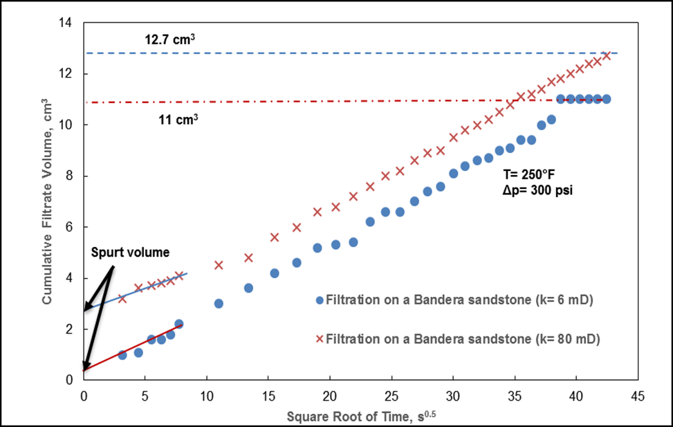
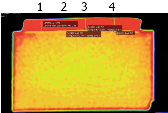
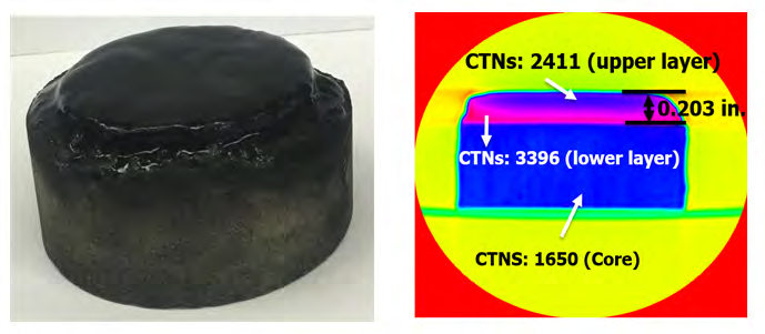
The tests were conducted for 30 min. The filtrate was collected in a graduated cylinder. The filter cake and the core disk were carefully removed and the filter cake thickness was determined after running each filtration test using CT scan. Figure 2 shows the cumulative filtrate volume (30 minutes) plotted against the square root of time. The cumulative filtration volumes using high-permeability and low-permeability Bandera sandstone disks were 12.7 and 11 cm3, respectively, at 300 psi and 250°F, which are acceptable filtration volumes (<15 cm3). This will decrease the mud invasion into the formation and cause less formation damage. Filter cakes generated by ilmenite water-based drilling fluid were thin, as determined by CT scan at four different location (Figure 3) with the average thickness of 0.203 ± 0.003 in.
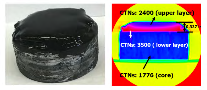
A CT scanner was used to investigate the filter-cake properties. Cross-sectional CT images were taken through the filter cake and the used disk and analyzed using a commercial software. The filter-cake thickness and CT numbers (CTNs) were determined. CT scanner is a powerful tool that had been used thoroughly to investigate filter cake properties [29, 30, 31, 32]. CT attenuation data are normally presented in an internationally standardized scale in Hounsfield units (HU). The CTNs for air and water are –1000 and 0.0 HU, respectively, which are used for normalizing this unit. Thus, each HU represents a 0.1% change in density with respect to the calibration‐density scale [33, 34]. CT scan images showed that the filter cake contained two layers with different CTNs. Figure 4 shows the Bandera sandstone core disk on the left after static filtration with the black filter cake on the top. On the right, the CT image shows that the average thickness of the filter cake is 0.337 in. The CTNs stand for the relevant density. With a higher CT number, the density of the material will be higher. The average CTN for the core disk was 1776 HU. The CTNs for the upper (close to the drilling fluid) and lower (close to the formation) layers of the filter cake were
2400 and 3500 HU, respectively. Figure 5 presents a Berea sandstone core disk with the black filter cake on the top. The two layers showed average CTNs of 2411 HU for the upper layer and 3396 HU for the lower layer. The CTN of the core disk was 1650 HU and the thickness of the filter cake was 0.203 in.
To better understand the two layers of the filter cakes, SEM-EDS was used to both visualize and quantify their elemental composition. Table 6 shows the elemental composition of the upper and lower layers of the filter cake generated using the ilmenite water-base drilling fluid through Berea sandstone disk at 300 psi and 250°F. Both layers contain more than 50 wt% iron and 30 wt% titanium.
The amount of potassium and chloride came from the drilling fluid, in which 72 g KCl was added to inhibit shale and to increase the density of the drilling fluid. Calcium also came from the drilling fluid. Calcium carbonate was added as the bridging material. The SEM-EDS analysis also revealed other elements, which may come from the chemicals used to prepare the drilling fluid.
| Upper Filter Cake Layer | Lower Filter Cake Layer | ||
|---|---|---|---|
| Element | Concentration (wt%) | Element | Concentration (wt%) |
| Fe | 55.86 | Fe | 51.73 |
| Ti | 29.66 | Ti | 29.03 |
| Mg | 5.1 | Mg | 4.96 |
| Si | 2.54 | Si | 2.51 |
| Cl | 2.79 | Cl | 3.56 |
| K | 2.44 | K | 3.09 |
| Ca | 1.61 | Ca | 1.61 |
| Al | 0 | Al | 3.51 |
| Sum | 100 | Sum | 100 |
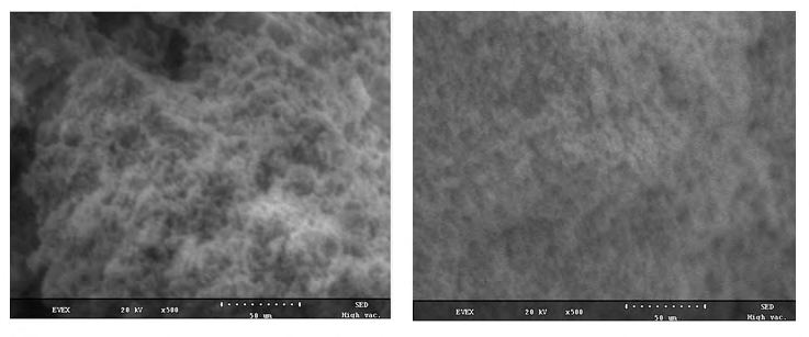
The elemental analysis (in wt%) indicates relatively similar composition of the upper and lower layers of the filter cake. Figures 6 shows the SEM images of those layers under X500 magnification. More pores were observed in the upper filter cake, whereas the lower layer was denser and more compact. The difference stems from the way in which the filter cakes are deposited. At first, the high-density, heavy weighting materials start to deposit on the surface of the formation. Later, smaller and lighter materials deposit on the top part of the filter cake [35, 36]. The lower filter cake layer is in a continuous compaction until the end of the filtration.
Elkatatny, et al. [10, 11] used bentonite-based drilling fluid, with at most 50 g weighting material. They found that the filter cake layer closer to the formation contained mainly the weighting material whereas the layer closer to the drilling fluid contained other materials. In our study, the drilling fluid formulation contains 300 g of weighting material. Thus, the filter cake was composed mainly of the weighting material with minor amounts of other materials.
Filter Cake Removal
The solubility of ilmenite by acids particularly is widely used in industrial processes to obtain TiO2 for pigment application. A brief summary of the reaction of ilmenite with different acid systems was reported by Elkatatny, et al. [13]. In our study, acid solutions were prepared and mixed with a corrosion inhibitor. Either 7.5 wt% HCl + 1 vol.% corrosion inhibitor or 7.5 wt% HCl + 7.5 wt% HEDTA + 1 vol% corrosion inhibitor solutions are tested. The combination was then soaked with the core and the filter cake inside the filter press for six hours at 300 psi and 250°F to simulate the real conditions. Effluent solution, after reaction, was collected, filtered, and diluted at 2000, 1000, 500, and 400 times with DI-water and analyzed by ICP to determine the amounts of cations. The remaining filter cake was analyzed by SEM-EDS to determine the composition.
The first attempt used 7.5 wt% HCl with 1 vol% corrosion inhibitor for six hours soaking time. Figure 7 shows the filter cake after static filtration, after treatment with 7.5 wt% HCl for six hours, and finally after drying at 212°F for three hours. Partial filter cake remained on the surface of the core disk, indicating an incomplete removal. Figure 8 shows a 3D model of the filter cake using CT scan. On the left side, after static filtration, some drilling fluid invasion can be observed, which may be due to the bridging process. On the right side, after reacting with 7.5 wt% HCl for six hours, more filtration into the core was observed.
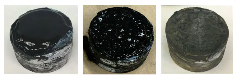
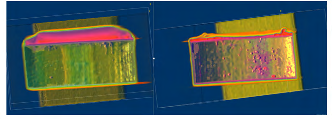
Table 7 shows the different weights of the core disk used in the 7.5 wt% HCl treatment. The dry weight of the core disk was 168.4 g, and weight in wet conditions, after saturation with 5 wt% KCl, was 178.2 g. After static filtration, the core with the filter cake weighed 219.7 g. Later, after the filter cake removal, the core with filter cake residue weighed
191.4 g. Compared to the saturated core, weighing 178.2 g, the filter cake removal was incomplete. The remaining filter cake and the core were also dried and compared with the initial conditions, which confirming incomplete removal of the filter cake.
| Dry Weight (g) | Wet Weight (g) | |
|---|---|---|
| Core disk | 168.4 | 178.2 |
| Core disk with filter cake | – | 219.7 |
| Core disk with the remaining filter cake | 179.8 | 191.4 |
Table 6: Different weights of the core disk and filter cake used in the acid treatment for six hours with 7.5 wt% HCl.
The second treatment attempt was conducted using acid solution of 7.5 wt% HCl + 7.5 wt% HEDTA + 1 vol% corrosion inhibitor at 300 psi and 250°F. Table 8 shows the pH, density, and acid concentration changes before and after the treatment. pH was 0 before and 0.3 after the treatment. Density increased from 1.078 to 1.124 g/cm3. The concentration of HCl decreased from 7.5 to 2.13 wt%. Table 9 compares the different weights of the core disk before and after the reaction. The dry weight of the core was 169.4 g, and after saturation with 5 wt% KCl, the core weighed 182.8 g. After static filtration, the core with the filter cake weighed 238 g, and after the treatment with acid combination, the weight was 199.7 g. Compared with the wet weight of the core, the remaining filter cake still existed on the surface of the core. Therefore, this attempt also resulted in a partial filter cake removal.
| Value | Before Treatment | After Treatment |
|---|---|---|
| pH | 0 | 0.3 |
| Density (g/cm3) | 1.078 | 1.124 |
| HCl Concentration (wt%) | 7.5 | 2.13 |
Table 7: pH, density, HCl concentration before and after the acid treatment for six hours with 7.5 wt% HCl and 7.5 wt% HEDTA.
| Dry Weight (g) | Wet Weight (g) | |
|---|---|---|
| Core disk | 169.4 | 182.8 |
| Core disk with filter cake | – | 238 |
| Core disk with remaining filter cake | – | 199.7 |
Table 8: Different weights of the core disk and filter cake used in the acid treatment for six hours with 7.5 wt% HCl and 7.5 wt%
Figure 9 shows the filter cake after static filtration and after soaking with 7.5 wt% HCl and 7.5 wt% HEDTA for six hours at 300 psi and 250°F. Remaining filter cake was observed. Figure 10 shows CT scan images of the core disk with the filter cake before and after the treatment. Before using acid, the thickness of the filter cake was 0.337 in., and after the treatment it became 0.094 in. The average CTNs of the filter cake after static filtration was 2400 HU for the upper layer and 3500 HU for the lower layer. After the reaction with the acid-chelate combination, the upper layer had been removed, and the CTNs of the lower layer became 3200 HU. Incomplete filter cake removal also occurred when using 7.5 wt% HEDTA with 7.5 wt% HCl at 300 psi and 250°F for six hours. In the past literature, weight difference was used to calculate the removal efficiency after acid-treatment. However, it is not an accurate method because it neglects the dissolution of the core. The acid will react with the filter cake as well as the core. Thus, the result obtained by using weight loss is not the true removal efficiency. In our research, if we ignored the dissolution of the core for the purpose of comparing with the past literature, the following equation should be used;
- Re % -
Wt Wt moval Efficiency Wt Wt
core cake core remaining cake + +
+ = (2) core cake core
where; core cake Wt + = the wet weight of the core disk and filter cake, core remaining cake Wt + = the wet weight of the core disk and the remaining filter cake, ad core Wt = the wet weight of the core before the experiment.
Based on this equation the removal efficiency when conducting the acid treatment for six hours with 7.5 wt% HCl was 68.2%, Additionally, the removal efficiency when conducting the acid treatment for six hours with 7.5 wt% HCl + 7.5 wt% HEDTA was 69.2%. The calculated removal efficiencies showed that HCl was the dominant acid in the removing process with minimal removal effect of 7.5 wt% HEDTA; however, HEDTA played a key role in reducing the corrosion issues as will be presented in the following sections.
Previous literature [12, 15] presented higher removal efficiency of ilmenite filter cake using HCl acid and chelating agents; however, they used higher soaking time and did not discuss the corrosion issues. For instance, Elkatatny, et al. [12] conducted the experiments using a soaking time of 16 hours and reported almost 100% removal efficiency when using 5 wt% of HCl and almost 48% removal efficiency when using 20 wt% of HEDTA as stand-alone acid.
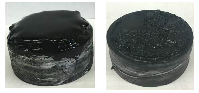
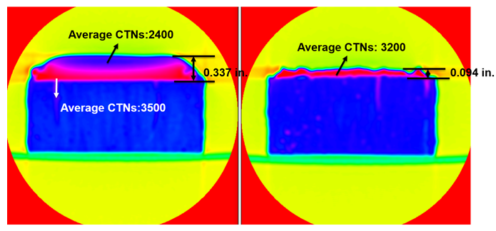
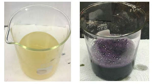
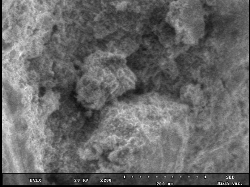
Figure 11 shows the solution color before and after the treatment. The yellow color came from the corrosion inhibitor. The purple color after the reaction was abnormal and rarely seen in the lab. Table 10 presents the elemental composition of the effluent solution after the reaction as revealed using ICP elemental analysis. The effluent solution contains large amount of iron (23,530 ppm) and sharply contrasted with titanium at 71 ppm. Calcium, magnesium and aluminum were also detected by ICP. The sandstone core disk minerals have calcium, magnesium, and aluminum, which confirms the acid reaction with the core. HEDTA complexes with Cr3+ and changed the color of the solution [37]. Abnormal high concentrations of Ni and Cr were also observed, which are a sign of corrosion. Figure 12 shows the SEM of the remaining filter cake after the treatment. Before the removal, the filter cake’s lower layer was smooth, dense, and compact. After the treatment, more pores were generated, which is a sign of the partial filter cake removal. Some of the particles aggregated and formed new structures.
| Element | Fe | Ti | Ca | Mg | Al | Ni | Cr |
|---|---|---|---|---|---|---|---|
| Concentration (ppm) | 23,530 | 71 | 1,982 | 374 | 252 | 2,851 | 4,616 |
Table 9: Cation concentration in the effluent solution after reaction with 7.5 wt% HCl and 7.5 wt% HEDTA.
The filter cake was not removed completely, and the acid was not fully spent. The concentration of the acid after the reaction, as determined by acid titration, was 2.13 wt%. Compared to the initial HCl concentration, almost 71.6% of the acid was spent. Van Dyk, et al. [24] discussed the mechanism of ilmenite leaching and concluded that titanium could polymerize in HCl. Low initial mole ratio of the acid-to- ilmenite will cause titanium polymerization, which forms a product layer. After forming this layer, the acid is separated from the remaining filter cake, and no more reaction can take place. Precipitation of TiOCl2 would occur in the pores of the particles. The start point of polymerization of titanium occurs when the concentration of titanium is larger than 10-3 mol/cm3. Almost 71 ppm of titanium, as determined by ICP, if divided by the molecular weight of titanium (47.867) is 1.48×10⁻³ mol/cm3. Therefore, titanium polymerized in the solution and mass-transfer limits the reaction. Van Dyk, et al. [24] recommended higher initial acid-to-ilmenite mole ratio to delay the polymerization of titanium and allow much more titanium to dissolve from ilmenite.
Summary and Conclusions
Ilmenite water-based drilling fluid was prepared and used to generate filter cake under static filtration using HP/ HT filter press at 300 psi differential pressure and 250°F. CT scan, SEM-EDS, and ICP were used to characterize the filter cake before and after soaking with HCl-HEDTA solution for six hours. Different attempts were conducted in order to remove the ilmenite-based filter cake. Based on the obtained results, the following conclusions can be drawn:
- The filter cake generated by ilmenite water-based drilling fluid consists of two layers as observed by CT scan and confirmed by SEM-EDS. The two layers were different in density, which led to different CTNs. SEM showed fewer pores in the upper layer. The lower layer was denser and more compacted with similar elemental compositions of the two layers as revealed by EDS. The bottom layer was harder to be removed than the upper layer.
- Removal of filter cake generated by ilmenite water- based mud with low-acid concentration of (7.5 wt% HCl) was partially completed as observed by both weight difference and CT scan.
- Using HEDTA as chelate with the acid solution is a good choice to prevent iron precipitation in the solution. However, corrosion issues were noticed. The acid solution color changed from yellow to purple, which resulting when HEDTA complexes with Cr3+. A special cell (Hastelloy) is recommended instead of stainless steel to minimize corrosion issues.
- The combination of 7.5 wt% HCl with 7.5 wt% HEDTA can partially remove the filter cake. Unspent acid and remaining filter cake indicate the polymerization of titanium, which could separate ilmenite from the acid and stop the reaction.
This study showed lab results to characterize and remove the filter cake generated by ilmenite water-based mud with lower concentration of acids. A better characterization will promote removing the filter cake effectively and completely.
With incomplete filter cake removal, more cost and benefit analysis should be done before apply in the field.
Acknowledgements
The first and second authors would like to acknowledge Prof. Hisham A. Nasr-El-Din, who passed away on July 3, 2020. May Allah forgive his sins, have mercy on him, and admit him Jannatul Firdauss. The authors would also like to express appreciation for Dr. Sarah Elnekhaily for proof reading this paper.
References
-
Sandera R (2006) Global Natural Gas Reserves-A Heuristic Viewpoint (part 1 of 2). Middle East Economic Survey 49(11).
-
Al-Bagoury M, Steele CD (2012) A New, Alternative Weight Material for Drilling Fluids. IADC/SPE Drilling Conference and Exhibition, San Diego, California, USA.
-
Blomberg NE, Melberg B, Bøe A, Jacobsen EA, Aarrestad S (1984) Evaluation of Ilmenite as Weight Material in Drilling Fluids. Journal of Petroleum Technology 36(6): 969-974.
-
Rae P, Lullo GD, Ahmad AB (2001) Towards Environmentally-Friendly Additives for Well Completion and Stimulation Operations. SPE Asia Pacific Oil and Gas Conference and Exhibition, Jakarta, Indonesia.
-
Menzel D (1973) A New Weighting Material for Drilling Fluids Based on Synthetic Iron Oxide. Fall Meeting of the Society of Petroleum Engineers of AIME, Las Vegas, Nevada, USA.
-
Tuntland OB, Herfjord HJ, Lehne KA, Haaland E (1982) Iron Oxides as Weight Materials for Drilling Mud. Erdoel- Erdgas Z 97(8): 300-302.
-
Sloan JP, Brooks JP, Dear III SF (1975) A New, Nondamaging, Acid-Soluble Weighting Material. Journal of Petroleum Technology 27(1): 15-20.
-
Saasen A, Hoset H, Rostad EJ, Fjogstad A, Aunan O, et al. (2001) Application of Ilmenite as Weight Material in Water-Based and Oil-Based Drilling Fluids. SPE Annual Technical Conference and Exhibition, New Orleans, Louisiana, USA.
-
Amighi M, Shahbazi K (2010) Effective Ways to Avoid Barite Sag and Technologies to Predict Sag in HP/HT and Deviated Wells. SPE Deep Gas Conference and Exhibition, Manama, Bahrain.
-
Elkatatny SM, Nasr-El-Din HA, Al-Bagoury M (2012) Evaluation of Micronized Ilmenite as Weighting Material in Water-Based Drilling Fluids for HPHT Applications. SPE Kuwait International Petroleum Conference and Exhibition, Kuwait City, Kuwait.
-
Elkatatny SM, Nasr-El-Din HA, Al-Bagoury M (2013) Properties of Ilmenite Water-Based Drilling Fluids for HPHT Applications. International Petroleum Technology Conference, Beijing, China.
-
Elkatatny SM, Xiao J, Nasr-El-Din HA, Al-Bagoury M (2013) Using Hydrochloric Acid to Remove Ilmenite Water-Based Filter Cake in HPHT Applications. SPE European Formation Damage Conference and Exhibition, Noordwijk, Netherlands.
-
Xiao J, Nasr-El-Din HA, Al-Bagoury M (2013) Evaluation of Micronized Ilmenite as a Weighting Material in Oil-based Drilling Fluids for HPHT Applications. SPE European Formation Damage Conference & Exhibition, Noordwijk, The Netherlands.
-
Al-Bagoury M (2014) Micronized Ilmenite - A Non- damaging & Non-sagging New Weight Material for Drilling Fluids. SPE Bergen One Day Seminar, Bergen, Norway.
-
Xiao J, Nasr-El-Din HA, Al-Bagoury M (2015) Removal of Ilmenite Oil-based Filter Cake under HP/HT Conditions Using Hydrochloric Acid. SPE North Africa Technical Conference and Exhibition, Cairo, Egypt.
-
Al-Bagoury M, Revil P (2018) Innovative and Cost- Effective Invert-Emulsion Fluids for Drilling Complex Wells. IADC/SPE Asia Pacific Drilling Technology Conference and Exhibition, Bangkok, Thailand.
-
Ivan C, Al Katheeri YS, Reichle M, Akyabi K, Ryan JT, et al. (2018) The Evolution of Nondamaging Fluid Design and Implementation Offshore Abu Dhabi. Abu Dhabi International Petroleum Exhibition and Conference, Abu Dhabi, UAE.
-
Feder J (2019) Nonaqueous, Nondamaging Fluid Implemented Offshore Abu Dhabi. Journal of Petroleum Technology 71(11): 57-60.
-
Razak MSA, Ezani FS (2020) First Successful Utilisation of High Density Micronised Ilmenite in South East Asia. SPE Offshore Technology Conference Asia, Kuala Lumpur, Malaysia.
-
Ibrahim AF, Al-Mujalhem MQ, Nasr-El-Din HA, Al- Bagoury M (2020) Evaluation of Formation Damage of Oil-Based Drilling Fluids Weighted with Micronized Ilmenite or Micronized Barite. SPE Drilling & Completion 35(03): 402-413.
-
Li J, Li Q, Li N, Teng X, Ren L, et al. (2019) Ultra-High Density Oil-Based Drilling Fluids Laboratory Evaluation and Applications in Ultra-HPHT Reservoir. SPE/IATMI Asia Pacific Oil & Gas Conference and Exhibition, Bali, Indonesia.
-
Li Q, Li S (2020) Ultra-High Density Oil-Based Drilling Fluids and its Applications in Ultra-Deep Petroleum Systems. SPE Latin American and Caribbean Petroleum Engineering Conference, Virtual.
-
Moreira RN, Jeughale R, Takahiro T, Motohiro T, Andrews K, et al. (2021) Best Practice to Improve Slim Hole Maximum Reservoir Contact Well Drilling Performance. SPE/IADC Middle East Drilling Technology Conference and Exhibition, Abu Dhabi, UAE.
-
Van Dyk JP, Vegter NM, Pistorius PC (2002) Kinetics of Ilmenite Dissolution in Hydrochloric Acid. Hydrometallurgy 65(1): 31-36.
-
Smith CF, Crowe CW, Nolan III TJ (1969) Secondary Deposition of Iron Compounds Following Acidizing Treatments. Journal of Petroleum Technology 21(9): 1121-1129.
-
Talyor KC, Nasr-El-Din HA, Al-Alawi MJ (1999) Systematic Study of Iron Control Chemicals Used During Well Stimulation. SPE Journal 4(1): 19-24.
-
API RP13B-1. Recommended Practice for Field Testing Water-Based Drilling Fluids.
-
Bourgoyne AT, Millheim KK, Chenevert ME, Young FS (1991) Applied Drilling Engineering. Volume 2, SPE Textbook Series, Richardson, TX, USA.
-
Vryzas Z, Mahmoud O, Nasr-El-Din HA, Kelessidis VC (2015) Development and Testing of Novel Drilling Fluids Using Fe2O3 and SiO2 Nanoparticles For Enhanced Drilling Operations. International Petroleum Technology Conference (IPTC), Doha, Qatar.
-
Mahmoud O, Nasr-El-Din HA, Vryzas Z, Kelessidis VC (2018) Using Ferric Oxide and Silica Nanoparticles to Develop Modified Calcium Bentonite Drilling Fluids. SPE Drill & Compl 33(1): 12-26.
-
Mahmoud O, Nasr-El-Din HA, Vryzas Z, Kelessidis VC (2018) Effect of Ferric Oxide Nanoparticles on the Properties of Filter Cake Formed by Calcium Bentonite- Based Drilling Muds. SPE Drill & Compl 33(4): 363-376.
-
Mahmoud O, Nasr-El-Din HA (2021) Formation Damage Assessment and Filter Cake Characterization of Ca- Bentonite Fluids Enhanced with Nanoparticles. SPE Drill & Compl 36(1): 75-87.
-
Wellington SL, Vinegar HJ (1987) X-Ray Computerized Tomography. Journal of Petroleum Technology 39(8): 885-898.
-
Akin S, Kovscek AR (2003) Computed Tomography in Petroleum Engineering Research. Geol Soc Lond 215(1): 23–38.
-
Civan F (1994) A Multi-Phase Mud Filtrate Invasion and Wellbore Filter Cake Formation Model. International Petroleum Conference and Exhibition of Mexico, Veracruz, Mexico.
-
Civan F (1996) A Multi-Purpose Formation Damage Model. SPE Formation Damage Control Symposium, Lafayette, Louisiana, USA.
-
De Wolf CA, Nasr-El-Din HA, Bouwman A, Bang ER, Naylor E (2012) A New, Low Corrosive Fluid To Stimulate Deep Wells Completed With Cr-based Alloys. SPE International Conference & Workshop on Oilfield Corrosion, Aberdeen, UK.
- Nigeria’s Vulnerability in the Face of Global Energy Policy
- A Simulation Study of Investigation of Optimum Oil Production Performance by Applying Various Gas Injection Methods in Oil Reservoir
- Characterization of Permo-Triassic Reservoirs through Thermal Maturity Assessment of Westphalian Source Rocks in the Cheshire Basin
- Influence of Microwax on the Rheological and Thermal Behaviour of a Wax Crude Oil
- Real-Time Monitoring and Performance Optimization of Steam Injection in Heavy Oil Reservoirs Using Fiber Optic Sensing and Integrated Predictive Simulation Models
- Rapid On-Site Determination of the Total Petroleum Hydrocarbon Content of Soils by Handheld Fourier Transform Near-Infrared Spectroscopy: Development of a Global, Site- and Scanner- Independent Calibration Model