Effect of Fluid Contact Angle of Oil-wet Ceramic Fracture Proppant on the Water Flow from Sandstones to Proppant Packs
Ceramic fracture proppants are extensively used for enhancing oil and gas well productivity in low-permeability reservoirs. Previous work reported attracting-oil-repelling-water (AORW) property of oil-wet proppants at the faces of fractures. Because of lack of method for measuring contact angle of proppant packs, the terms water-wet proppant and oil-wet proppant were defined on the basis of observations of liquid droplets on the surfaces of proppant packs without quantitative measurement. An innovative method was developed in this study to determine the contact angles of fracture proppant packs. The effect of oil contact angle of oil-wet fracture proppant pack on the competing water/oil flow from sandstone cores to the packs was investigated. It was found that, for a given fracture proppant pack, the sum of the water contact angle and oil contact angle measured in the liquid-air-solid systems is less than 180 degrees, i.e., the two angles are not supplementary. This is believed due to the weak wetting capacity of air to the solid surfaces in the liquid-air-solid systems. Both water and oil contact angles should be considered in the classification of wettability of proppant packs. Fracture proppant packs with water contact angles greater than 90 degrees and oil contact angles significantly less than 90 degrees can be considered as oil-wet proppants. Reducing oil contact angles of oil-wet proppants can increase capillary force, promote oil imbibition into the proppant packs, and thus improve the AORW performance of proppants. Fracture proppant packs with water contact angles less than 90 degrees and oil contact angles less than 90 degrees may be considered as mixed-wet proppants. Their AORW performance should be tested in laboratories before they are considered for well fracturing operations.
Introduction
Ceramic fracture proppants are extensively used for enhancing oil and gas well productivity in low-permeability reservoirs. The matrix/fracture interaction and its effect on well productivity and hydrocarbon recovery are described by Mao D, et al. [1]; Longoria RA, et al. [2]; Le TD, et al. [3]; Zhang F, et al. [4] & Zhu H, et al. [5] give insights for understanding the mechanical behavior of proppants in hydraulic fractures. Several fracture and proppant parameters in fracturing oil and gas wells have been thoroughly studied Safari R, et al. [6] except the impact of proppant’s surface wetting property on the behavior of oil and gas wells.
proppant packs to study the effect of surface wettability of ceramic proppant on the oil flow efficiency from core samples to fractures filled with CC (code for proppant provider) proppants. He observed that oil-wet proppant increased oil flow efficiency from sandstone to proppant packs. The mechanism is interpreted as the oil imbibition-induced oil flow channels across the sand-fracture interface. That is, oil-wet proppants have a common property of attracting-oil- repelling-water (AORW) at the interface between sandstone and proppant pack. Dong K, et al. [8] further investigated the effect of wettability of CC proppant surface in guar gum solution on the oil flow efficiency in fractures. They concluded that the residual guar gum in the fractures has negative effect on improving oil-flow efficiency. Dong K, et al. [9] investigated the effects of oil-wet and mixed-wet surfaces of ceramic proppants on the oil flow using Scanning Electron
Microscopy and energy-dispersive system and found that the resin-coated oil-wet proppant surface is much smoother than that of the mixed-wet proppant. Based on the result of oxide analysis, there is a layer of oleophilic materials which causes the oil affinity of the oil-wet proppants. However the mixed- wet proppant presents dual affinity of oil and water due to capillary cohesion. They also concluded that the surface wettability plays a more essential role in determining the competing flow of oil and water in small size proppant than in large size proppant. As the proppant size increases, the effect of surface wettability on hydrogen transfer diminishes. Xiao D, et al. [10] investigated the AORW property of PC (code for proppant provider) proppants and verified Dong K, et al. [7] work. Zha C, et al. [11] showed that the use of proppant surface alternation agents significantly reduced proppant flow back and resulted in higher hydrocarbon production when compared to conventional proppants used in offset wells. Chaplygin D, et al. [12] presented their experience with using largemesh-size proppants to improve well productivity in mid-permeable reservoirs. Tabatabaei M, et al. [13] showed how surface modification of proppant by hydrophobic coating enhanced long-term production of wells. Xiong H, et al. [14] demonstrated the effects of proppant surface wettability on the horizontal well performance.
However, in all the previous work the terms water-wet prpppant and oil-wet proppant were defined on the basis of observations of liquid droplets on the surfaces of proppant packs without quantitative measurement. It is highly desirable to quantify the wettability of proppant packs using a measurable parameter so that the AORW behavior of proppants can be better described.
Solid surface wetting behavior is characterized by the level of hydrophobicity and hydrophobicity on the basis of contact angle. Washburn EW, et al. [15] developed a relationship between contact angle and capillary flow rate. Giese RF, et al. [16] presented a thin layer wicking method to measure the contact angles on small particles by measuring the capillary flow rate of a liquid. Giese RF, et al. [17] measured contact angle between water and caffeine particles by using glass slide method, compacted plate method, and inverse gas chromatography (IGC) method. Awasthi A, et al. [18] proposed an optical method to measure the contact angle between mercury and graphite at room temperature. Hung YL, et al. [19] proposed a modified selected plane method to find the real contact point and avoid image distortion effect for calculating the superhydrophobic contact angle based on droplet apex, height and two interfacial loci. Meiron TS, et al. [20] measured contact angle of water and ethylene glycol on rough beeswax surfaces using a vertically vibrating method to make the drop reach the lowest energy to calculate the apparent contact angle from drop diameter and weight. Cui ZG, et al. [21] measured the contact angle for highly porous silica gel using the thin layer wicking method and found a discrepancy in liquid penetration velocity between the unsaturated and pre-saturated silica. Iliev S, et al. [22] presented a numerical model to determine contact angle of no axisymmetric drops when contact line of the drop is available. Chini SF, et al. [23] presents a sub-pixel polynomial fitting (SPPF) method to measure the contact angle of symmetric and asymmetric drops without using any liquid property value. Liu TL, et al. [24] proposed a new method to investigate fluid dynamic contact angles with less than 1.0 mm capillary length on super omni phobic surfaces. However, none of these methods can be used to measure the contact angles of solid particles and particle packs due to small particle sizes and their non-flat surfaces.
On the basis of geometric relation of parameters of liquid droplets at solid surfaces, an analytical method was developed in this work for determining the liquid contact angle from measured the volume and diameter data of droplets. The new method was validated through comparison of the water contact angles at stainless steel surfaces measured in this work and literature. The difference between the results is within 3 %, indicating the reliability of the new method. Packs of two CP proppants were tested with the new method to determine their contact angles of water and oil. The AORW property of these proppant packs was also tested. This work provides a more rigorous means of quantifying the AORW property of fracturing proppants through contact angle measurement.
Experimental Design
Sandstone Core Sample
Two sandstone core samples with permeability contrast of about 6 fold were selected in this study. They are Parker Berea Sandstone (PB-SS) and Upper Grey Berea Sandstone (UGB-SS). Petrophysical properties of them are summarized in (Table 1).
| Petrophysical Properties | PB-SS | UGB-SS | ||||
|---|---|---|---|---|---|---|
| Core 1 | Core 2 | Core 1 | Core 2 | Core 3 | Core 4 | |
| Porosity (%) | 16.19 | 15.81 | 19.2 | 19.25 | 19.27 | 19.06 |
| Water Permeability (md) | 8 | 9 | 68 | 68 | 52 | 49 |
| Water Saturation (%) | 50.2 | 50.1 | 45.4 | 45.3 | 45.4 | 45.5 |
Table 1: Petro physical Properties of Some Berea Sandstone Samples.
Fracture Proppant
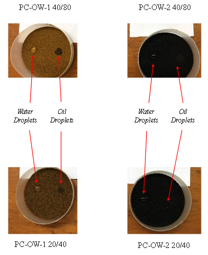
The effect of fluid contact angle of proppant pack on the AORW behavior of proppants was investigated using 4 PC proppant samples namely PC-OW-1 40/80, PC-OW-2 40/80, PC-OW-1 20/40, and PC-OW-2 20/40 as shown in (Figure 1). The water and oil droplots were first placed at the prpoppant pack surfaces to roughly infor surface wetting behavior. Oil droplets were found not clearly visible due to low contrast in colors and liquid sinking into the prpppant packs due to gravity. Water and oil contact angles were then determined using the method described in Appendix A in water-air-solid and oil-air-solid systems respectively. Measured droplet paramers and calculated contact angles for summarized in (Table 2). The result is very consistent with the measurtements given by Al-Boghail F, et al. [25] for neutral wet HSP proppants. Because the oil contact angles are less than the water contact angles, these proppant packs are considered oil-wet. Judging from the oil contact angles, PC-OW-2 40/80 is more oil-wet than PC-OW-1 40/80, and PC-OW-2 20/40 is more oil-wet than PC-OW-1 20/40.
| Proppant Sample | Droplet Volume (cc) | Droplet Diameter (cm) | Calculated Contact Angle (deg) | |||
|---|---|---|---|---|---|---|
| Water | Oil | Water | Oil | Water | Oil | |
| PC-OW-1 40/80 | 0.045 | 0.025 | 0.4313 | 0.515 | 114.91 | 75.58 |
| PC-OW-2 40/80 | 0.045 | 0.025 | 0.534 | 0.777 | 94.47 | 29.63 |
| PC-OW-1 20/40 | 0.045 | 0.025 | 0.459 | 0.551 | 109.01 | 67.08 |
| PC-OW-2 20/40 | 0.045 | 0.025 | 0.701 | 0.857 | 61.45 | 22.5 |
Table 2: Measured Droplet Paramers and Calculated Contact Angles.
Experimental Setup
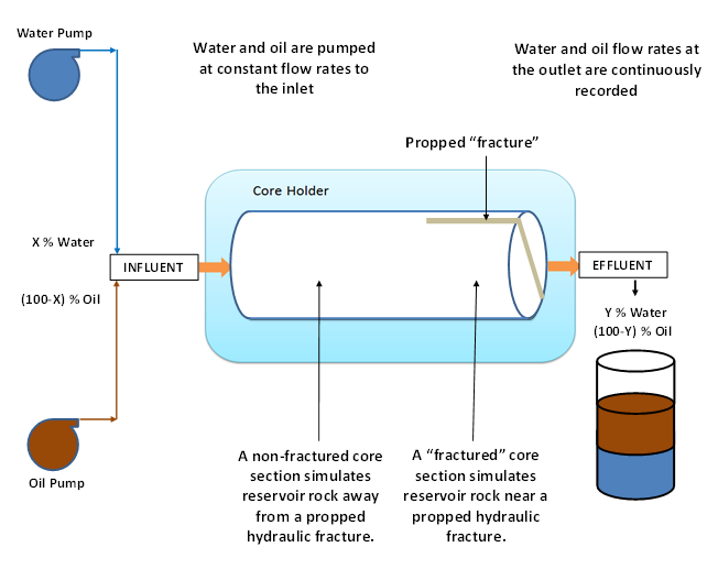
The experimental apparatus employed in this study is shown in (Figure 2). The central component is a 2-foot long core holder assembly that uses confining gas pressure for tightening a rubber sleeve to seal a 2-inch diameter, 20-inch long, sandstone core sample. A 6-inch long slot is cut along the diameter of the core to simulate a hydraulic fracture. The “fracture” is filled with proppant particles before testing [26, 27].
Experiment Procedure
- The experimental procedure is outlined as follows:
- Measure the dimension and dry weight of a sandstone core sample.
- Remove the air in the core sample by vacuum in a water chamber.
- Measure the wet weight of the core sample, calculate pore volume (PV) and core sample porosity. Transfer the wet core sample into the core holder, seal the core with confining pressure, inject water through the core, and calculate core permeability.
- Inject oil (43o API)into the core until the desired water saturation (45% to 50%) is reached.
- Remove the core sample from the core holder and cut a 6-inch long (0.1 inch and 0.2 inch wide) “fracture” along the diameter of the core.
- Fill the “fracture” with proppant particles, transfer the core sample into the core holder, and seal the core with confining pressure.
- Inject water and oil with deigned water-cut 40 % at 5cc/min through the core and record water and oil-flow volumes every one minute at the outlet.
- Stop fluid injection when the effluent water-cut reaches the influent water-cut.
Experimental Result
Figure 3 presents a comparison of water cut profiles for systems with PC-OW-1 40/80 and PC-OW-2 40/80 proppants in 0.1 inch fractures in PB-SS cores. It shows that water breaks through in to the PC-OW-1 40/80 proppant pack at 0.27PV of two-phase injection and water breaks through in to the PC- OW-2 40/80 proppant pack at 0.36 PV of two-phase injection. The delayed water breakthrough time into the PC-OW-2 40/80 is expected because this proppant pack has an oil contact angle (29.63o) that is lower than the oil contact angle of the PC-OW-1 40/80 proppant pack (75.58o), while both prpppant packs have water contact angles of greater than 90o.
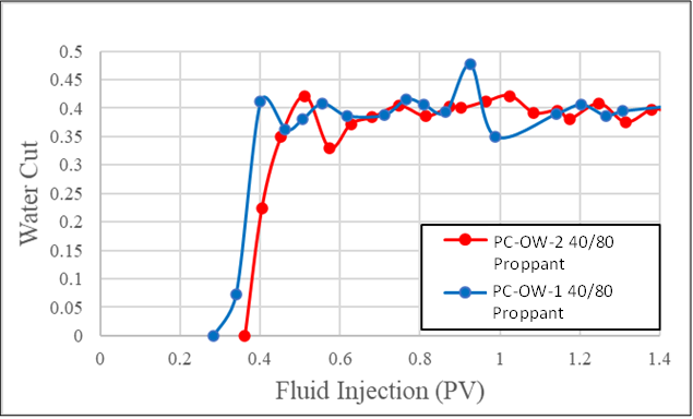
Figure 4 shows a comparison of water cut profiles for systems with PC-OW-1 40/80 and PC-OW-2 40/80 proppants in 0.1 inch fractures in UGB-SS cores. It indicates that water breaks through in to the PC-OW-1 40/80 proppant pack at 0.34 PV of two-phase injection and water breaks through in to the PC-OW-2 40/80 proppant pack at 0.38 PV of two-phase injection. Again the delayed water breakthrough time into the PC-OW-2 40/80 is expected because the oil contact angle (29.63o) of this proppant pack is lower than that of the PC- OW-1 40/80 proppant pack (75.58o), while both prpppant packs have water contact angles of greater than 90o.
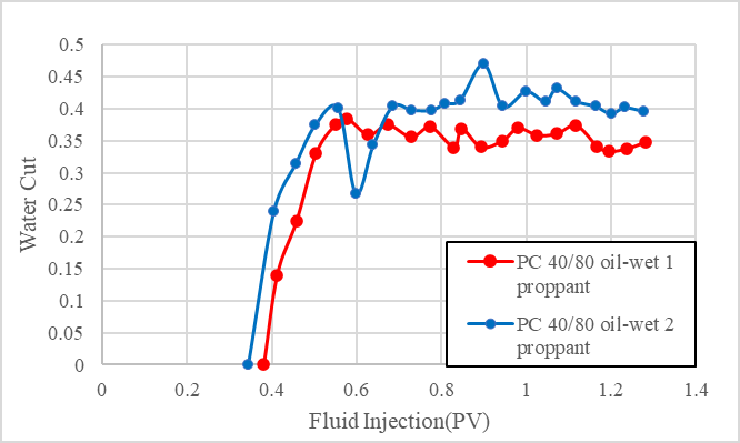
Figure 5 illustrates a comparison of water cut profiles for systems with PC-OW-1 20/40 and PC-OW-2 20/40 proppants in 0.2 inch fractures in UGB-SS cores. It shows that water breaks through in to the PC-OW-1 20/40 proppant pack at 0.36 PV of two-phase injection and water breaks through in to the PC-OW-2 20/40 proppant pack at 0.33 PV of two- phase injection. It was expected that water breakthrough time into the PC-OW-2 20/40 would be delayed due to the lower oil contact angle of the proppant pack. However, this delay did not occur. The reason is believed to be due to the fact that the water contact angle for the proppant pack is less than 90o. Although its water contact angle 61.45o is higher than its oil contact angle 22.5o, the low water viscosity (1 cp) and high oil viscosity (4.7 cp) might cause accelerated water break through.
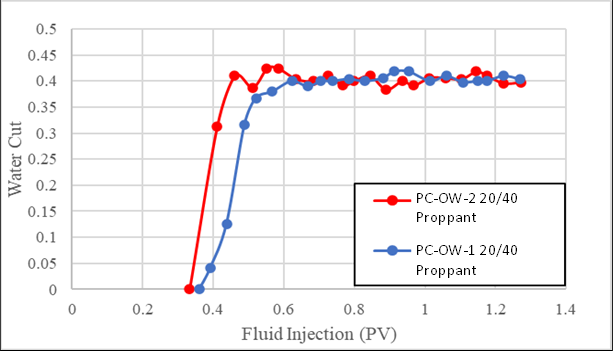
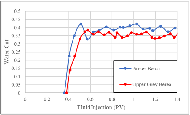
Figure 6 shows a comparison of water cut profiles for systems with PC-OW-1 40/80 proppants in 0.2 inch fractures in PB-SS and UGB-SS cores. It indicates that water breaks through in to the PC-OW-1 40/80 proppant pack in a PB- SS core at 0.36 PV of two-phase injection and water breaks through in to the PC-OW-1 40/80 proppant pack in a UGB- SS core at 0.38 PV of two-phase injection. This comparison implies an insignificant effect of sandstone petro physical properties on the water breakthrough, although the sandstone permeabilities are different in 6 fold.
Discussion
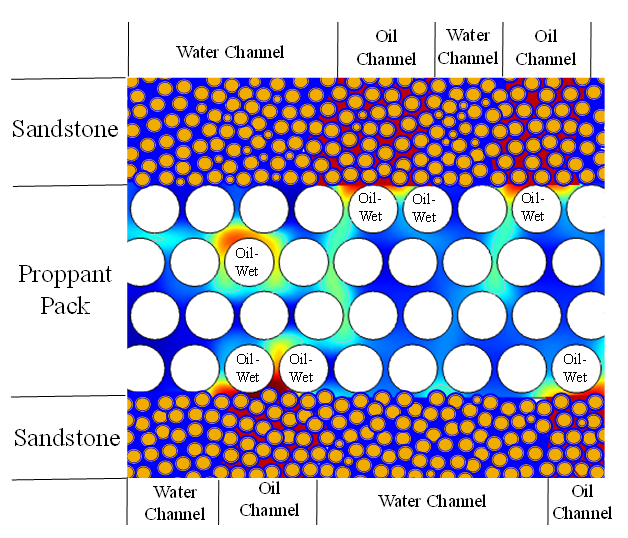
It is commonly known that the water contact angle and the oil contact angle are supplementary in water-oil-solid systems. However, it is noticed from Table 2 that, for a given proppant, the sum of the water contact angle and oil contact angle measured in the liquid-air-solid systems is less than 180o. This is believed due to the weak wetting capacity of air to the solid surfaces in the liquid-air-solid systems. Proppants PC-OW-1 40/80, PC-OW-2 40/80, and PC-OW 20/40 all have oil contact angles less than 90o and water contact angles great than 90o. These proppants can be classified as oil- wet proppants. However, proppant PC-OW-2 20/40 has an oil contact angle 22.5o and water contact angle 61.45o, both are low than 90o. It is not unclear if this proppant should be classified as an oil-wet proppant. The data in Figure 2 does indicate that this proppant delayed water breakthrough. This may be explained by the fact that the oil contact angle is much lower than the water contact angle for this proppant. Therefore, it can be considered as an oil-wet proppant. It is worthy to investigate the AORW performance of proppants that have similar water and oil contact angles in the future This experimental study shows that the effectiveness of oil-wet proppant for AORW depends on the oil contact angle on the surface of proppant pack. The mechanism of the oil-wet proppant promoting oil flow from sandstone to the proppant packs in fractures may be the affinity-induced oil imbibition inside the sandstone into the proppant pack. As illustrated in Figure 7, there may exist channels for water and oil flow in sandstones. This affinity-induced imbibition may result in the connection of oil flow channels inside the sandstone to the oil-wet proppant pack. The oil imbibition process is promoted by capillary pressure, which is a strong function of oil contact angle. The lower the contact angle is, the faster the oil imbibition is. The more the oil-wet proppants are, the more the connected oil channels are.
Conclusions
- An innovative method was developed for determining the contant anges of fracture proppante packs. Effect of oil contact angles of 4 oil-wet fracture proppant packs on the competing water/oil flow from sandstone cores to the packs were investigated in this study. Two sandstones (Parker Berea and Upper Gray Berea) with 0.1-inch and 0.2-inch wide “fractures” were used in this study. The following conclusions are drawn:
- For a given frature proppant pack, the sum of the water contact angle and oil contact angle measured in the liquid-air-solid systems is less than 180o, that is, the two angles are not supplementary. This is believed due to the weak wetting capacity of air to the solid surfaces in the liquid-air-solid systems. Both water and oil contact angles should be considered in the classification of wettability of proppant packs.
- Fracture proppant packs with water contact angles greater than 90o and oil contact angles significantly less than 90o can be considered as oil-wet proppants. Experimental result from testing with two sandstones and two fracture widths indicates that reducing oil contact angle of oil-wet proppant can improve the AORW performance of proppant packs through increasing capillary force and thus promoting oil imbibition into the proppant packs.
- Fracture proppant packs with water contact angles less than 90o and oil contact angles less than 90o may be considered as mixed-wet proppants.
Their AORW performance depends on water and oil viscosities and should be tested in laboratories before the proppant propants are considered for well fracturing operations.
Acknowledgement
The authors are grateful to BIRD for funding the project “Safe, sustainable, and resilient development of offshore reservoirs and natural gas upgrading through innovative science and technology: Gulf of Mexico-Mediterranean”, through Contract No. EC-19 Fossil Energy.
References
-
Mao D, Miller DS, Karanikas JM, Lake EA, Fair PS, et al. (2017) Influence of Finite Hydraulic-Fracture Conductivity on Unconventional Hydrocarbon Recovery with Horizontal Wells. Society of Petroleum Engineers 22(6): 1709-1807.
-
Longoria RA, Liang T, Huynh UT, Nguyen QP, DiCarlo DA (2017) Water Blocks in Tight Formations: The Role of Matrix/Fracture Interaction in Hydrocarbon- Permeability Reduction and Its Implications in the Use of Enhanced Oil Recovery Techniques. Society of Petroleum Engineers 22(5): 1393-1401.
-
Le TD, Murad MA, Pereira PA (2017) A New Matrix/ Fracture Multiscale Coupled Model for Flow in Shale-Gas Reservoirs. Society of Petroleum Engineers 22(1): 265- 288.
-
Zhang F, Zhu H, Zhou H, Guo J, Huang B (2017) Discrete- Element-Method/Computational-Fluid-Dynamics Coupling Simulation of Proppant Embedment and Fracture Conductivity After Hydraulic Fracturing. Society of Petroleum Engineers 22(2): 632-644.
-
Zhu H, Shen J, Zhang F (2018) A fracture conductivity model for channel fracturing and its implementation with Discrete Element Method. Journal of Petroleum Science and Engineering 172: 149-161.
-
Safari R, Lewis R, Ma X, Mutlu U, Ghassemi A (2017) Infill-Well Fracturing Optimization in Tightly Spaced Horizontal Wells. Society of Petroleum Engineer 22(2): 582-595.
-
Dong K (2018a) “Effect of Ceramic Proppant Surface Wettability on Oil Flow Efficiency in Hydraulic Fractured Wells”. International Journal of Engineering Research and Development 14(10): 13-22.
-
Dong K, Wang M, Zhang C (2018b) Effect of wettability of ceramic proppant surface in guar gum solution on the oil flow efficiency in fractures. Petroleum Journal 5(4).
-
Dong K, He W, Wang M (2019) Effect of surface wettability of ceramic proppant on oil flow performance in hydraulic fractures. Energy Science & Engineering 7(2): 504-514.
-
Xiao D, Wang M, Guo B, Weng D (2019) Effect of surface wetting behavior of ceramic proppant on the two-phase flow across the interface of sandstone and fracture. Energy Sci Eng 8(4): 1330-1336.
-
Zha C, Green J, Abrams B, Cabori L, Hamori K, et al. (2020) On-the-Fly Proppant Flow back Control Additive. Paper presented at the SPE Annual Technical Conference and Exhibition, Virtual.
-
Chaplygin D, Khamadaliev D, Chernyshev A (2020) Experience with 6/10 and 10/14 Mesh Size on Mid-Permeable Reservoirs. SPE Russian Petroleum Technology Conference. Virtual, SPE-202054-MS.
-
Tabatabaei M, Taleghani DA, Cai Y, Santos L, Alem N (2021) Surface Modification of Proppant Using Hydrophobic Coating To Enhance Long-Term Production. SPE Prod & Oper 36(1): 116-127.
-
Xiong H, Yoon S, Yu J (2021) A Novel Method to Speedup Calibrating Horizontal Well Performance Model with Multi-Stage Fracturing Treatments and Its Applications in Delaware Basin. Paper presented at the SPE Reservoir Simulation Conference On-Demand.
-
Washburn EW (1921) The dynamics of capillary flow. Physical review 17(3): 273.
-
Giese RF, Costanzo PM, van Oss CJ (1991) The surface free energies of talc and pyrophyllite. Phys Chem Minerals 17(7): 611-616.
-
Dove JW, Buckton G, Doherty C (1996) A comparison of two contact angle measurement methods and inverse gas chromatography to assess the surface energies of theophylline and caffeine. International Journal of Pharmaceutics 138(2): 199-206.
-
Awasthi A, Bhatt YJ, Garg SP (1996) Measurement of contact angle in systems involving liquid metals. Measurement Science and Technology 7(5): 753-757.
-
Hung YL, Chang YY, Wang MJ, Lin SY (2010) A simple method for measuring the superhydrophobic contact angle with high accuracy. Rev Sci Instrum 81(6): 065105.
-
Meiron TS, Marmur A, Saguy S (2004) Contact angle measurement on rough surfaces. Journal of Colloid and Interface Science 274(2): 637-644.
-
Cui ZG, Binks BP, Clint JH (2005) Determination of contact angles on microporous particles using the thin- layer wicking technique. Langmuir 21(18): 8319-8325.
-
Iliev S, Pesheva N (2006) Nonaxisymmetric drop shape analysis and its application for determination of the local contact angles. J Colloid Interface Sci 301(2): 677-684.
-
Chini SF, Amirfazli A (2011) A method for measuring contact angle of asymmetric and symmetric drops. Colloids and Surfaces A: Physicochemical and Engineering Aspects 388(1-3): 29-37.
-
Liu TL, Kim CJC (2017) Contact Angle Measurement of Small Capillary Length Liquid in Super-repelled State. Scientific reports 7(1): 740.
-
Al-Boghail F, Al-Moajil A, Al-Arawi A, Al-Darwish S (2020) Direct Approach for Contact Angle Measurement of Neutral Wet HSP Proppants. Paper presented at the SPE Asia Pacific Oil & Gas Conference and Exhibition. Virtual, pp: 202287.
-
(2003) Contact Angle and Surface Energy Measurements on Steel. First Ten Angstroms, pp:1-6.
-
(2022) Contact Angle of Water on Smooth Surfaces and Wettability. KINO. Appendix A: Derivation of an Equation for Determining Contact Angle on the basis of Droplet Measurement Figure A1 shows a liquid droplet placed on the smooth surface of a solid sample. If the volume of the droplet is known and the diameter of the droplet is measured on the surface, an equation can be derived to estimate the contact angle. Assuming that an amount of liquid dropped on the solid surface takes a shape of a truncated sphere, the shaded area in Figure A2 shows the cross-section of the liquid droplet. [INLINE_FIGURE:7:0] **Figure A1:** Procedure of placing a fluid droplet to the solid sample with smooth surface. [INLINE_FIGURE:7:1] **Figure A2:** Cross-section of a liquid droplet on the surface of a solid. The volume of the liquid phase is expressed as ( ) 2 2 3 6 V H S H π = + (A1) where _V_ is the volume, 2_S_ is the diameter of sphere, and _H_ is the height of the liquid droplet. If the volume _V_ is known before dropping and the diameter _S_ is measured after dropping, the _H_ can be solved from Eq. (A.1) to give 3 2 6 3 0 V H S H π + − = (A2) which gives a real root of [INLINE_TABLE:7:0] [INLINE_TABLE:7:1] (A3) where 2 3 B S = (A4) and 6V C π = (A5) Geometrical relation gives tan S H β = (A6) Because 2 π θ β − = , Equation (A6) becomes tan 2 S H π θ − = (A7) which results in 1 2tan S H θ π − = − (A8) **Method Validation:** Equation (A.8) was validated through a comparison of its result to that found in literatures for water-air-stainless steel system under ambient conditions. FTA [26] reported that the mean of the water contact angles is 75.7o, the standard deviation 1.6, and the coefficient of variance is 2.1%. KSI [27] provided new data of contact angle of water on the smooth surface of stainless steel 304. The reported water contact angle is between 70o and 75o. The average volume of the water droplets is 0.045 cc for 500 droplets measured in our lab at a room temperature of 72oC. The average diameter of the droplets on the steel surface is 0.6532 cm for 10 droplets. Equation (A.8) gives a contact angle of 70.33o, which is within the range given by KSI [27]. The difference is 3%. Therefore the new method is considered valid for determining liquid contact angle on the smooth surfaces of solid.
- Nigeria’s Vulnerability in the Face of Global Energy Policy
- A Simulation Study of Investigation of Optimum Oil Production Performance by Applying Various Gas Injection Methods in Oil Reservoir
- Characterization of Permo-Triassic Reservoirs through Thermal Maturity Assessment of Westphalian Source Rocks in the Cheshire Basin
- Influence of Microwax on the Rheological and Thermal Behaviour of a Wax Crude Oil
- Real-Time Monitoring and Performance Optimization of Steam Injection in Heavy Oil Reservoirs Using Fiber Optic Sensing and Integrated Predictive Simulation Models
- Rapid On-Site Determination of the Total Petroleum Hydrocarbon Content of Soils by Handheld Fourier Transform Near-Infrared Spectroscopy: Development of a Global, Site- and Scanner- Independent Calibration Model