Assessment of Potential Carbon Dioxide (CO2) Storage Capacity: An Examination in Ship Shoal, Gulf of Mexico
The surge in greenhouse gas emissions, particularly carbon dioxide (CO2), has necessitated the exploration of stable solutions for atmospheric CO2 reduction. CO2 sequestration in depleted oil and gas reservoirs is a widely embraced strategy due to its economic advantages from existing infrastructure. This research investigates the viability of depleted oil and gas blocks in the Ship Shoal field, Gulf of Mexico, as potential CO2 repositories. The study estimates the CO2 storage potential of six selected blocks (SS028, SS032, SS037, SS056, SS058, and SS072) using three methods: the DOE, CSLF method and the Agartan correlation. The DOE method yields a potential storage capacity of 4,509,763 tons of CO2, while the CSLF method estimates 5,139,030 tons, and the Agartan correlation yields 5,379,900 tons. The findings suggest that the studied blocks offer significant CO2 storage potential. However, as the analysis focused on a limited number of blocks, the overall storage capacity in the Gulf of Mexico region could be substantially higher when considering all potential sites. This research contributes to the evaluation of depleted oil and gas reservoirs as viable options for CO2 sequestration, addressing the pressing need for atmospheric CO2 reduction.
Introduction
Background
The emission of carbon dioxide (CO2), an impactful greenhouse gas, poses a significant challenge for the Thesis contemporary world, as it is a major worry in safeguarding the environment against the impending effects of global warming. The increasing use of industrial technologies and activities leads to a rise in CO2 emissions into the environment. Global energy consumption is projected to rise by 44% (678 quadrillion Btu from 472 quadrillion Btu) by 2030 [1]. Emissions of greenhouse gases (GHG) are released into the atmosphere, with CO2 being the predominant contributor, accounting for over 79% of the total GHG emissions in the United States in 2021 [2]. This has led to a corresponding increase in the average earth temperatures by 1.18°C or 2.12°F in 2023 (highest ever recorded) which is of anthropogenic cause [3]. Global carbon dioxide (CO2) emissions are anticipated to surge from 24 billion metric tons in the early part of this century to reach 37 billion metric tons by the year 2025 [4]. Also, the atmospheric CO2
concentration was estimated to reach 419.3 parts per million (ppm) in 2023 [5]. However, scientific evidence suggests limiting the global temperature anomaly to a range of 1.5-2°C above preindustrial levels is crucial to mitigate climate risks to the planet [6] (Figure 1).
![Figure 1: Global Temperature Anomaly [7].](/fulltextimages/12789/fig_1.png)
Parties to the United Nations Framework Convention on Climate Change UNFCCC came to a historic agreement on December 12, 2015, at COP 21, in Paris, to combat climate change and to step up and intensify the investments and activities required for a sustainable low-carbon future [8]. For that reason, the Paris Climate Agreement was signed in 2016 to maintain the average global temperature well below 2 °C (3.6 °F) over pre-industrial levels by 2050, preferably to 1.5 °C (2.7 °F). Therefore, the best way to break this loop of environmental harm is to reduce CO2 concentrations by storing the CO2 released into the atmosphere somewhere safe. This will limit the impact and allow for continuous regular energy use.
In response to the global rise in the planet Earth’s temperature and agenda Net Zero Emission (NZE) by 2050, various remedies have been discovered of which some are still under review, to curb this global concern.
There are several ways to lower CO2 emissions, such as cutting back on the use of fossil fuels, transitioning to fuels with lower carbon emissions, replacing fossil fuel technologies with carbon-free alternatives, improving natural systems’ ability to absorb carbon from the atmosphere, and utilizing carbon capture and storage [9]. Carbon capture and storage (CCS), of main interest, entails using technology to gather and concentrate CO2 produced from industrial and energy- related activities. Subsequently, the CO2 is transported to an appropriate storage location and stored away from the atmosphere for an extended duration [9].
Motivation
In 2021, global CO2 emissions related to energy increased by 6% to reach 36.3 billion tons, marking their highest recorded level. This surge was driven by a robust recovery of the world economy from the COVID-19 crisis, with a significant reliance on coal to fuel this growth [10]. The pursuit of technologies to reduce CO2 emissions has been motivated by a growing concern that the increasing atmospheric concentrations of (CO2) contribute to global climate change. The noticeable rise witnessed over the past two centuries is human-induced emissions linked to the burning of fossil fuels. A significant challenge for the modern world is the stabilization of anthropogenic atmospheric CO2 concentrations, requiring substantial reductions in CO2 emissions.
The motivation for this study arises from the pressing need to address the rising concentration of CO2 in the atmosphere, primarily driven by the combustion of fossil fuels—the primary source of energy. This phenomenon is further complicated by a contradictory increase in energy demand. As society faces this dual challenge, exploring viable solutions becomes imperative. The depleted reservoirs of Ship Shoal in the Gulf of Mexico offer a unique opportunity for carbon storage, providing a potential means to alleviate the adverse effects of heightened CO2 emissions. This study seeks to delve into the assessment of carbon storage potential in these reservoirs, contributing valuable insights to the broader discussions on sustainable energy practices and environmental preservation.
Objectives
The primary objectives of this study are to assess the suitability of depleted reservoirs in some blocks of Ship Shoal for CO2 storage by evaluating their geological and structural characteristics, and proximity to the shore of CO2, quantify the potential CO2 capacity through advanced modelling techniques, and explore optimal storage mechanisms.
Outline
The research focuses on investigating the viability of CO2 storage in some depleted reservoirs in Ship Shoal, Louisiana to address the escalating CO2 concentrations contributing to climate change. The introduction provides a contextual background, emphasizing the urgency prompted by the paradoxical rise in CO2 levels amidst increasing energy demands driven by fossil fuel combustion. The motivation underscores the necessity of exploring sustainable solutions, setting the stage for the research’s scope and objectives. The research aims to assess geological suitability and quantify storage capacity comprehensively. The literature review delves into storage mechanisms, and feasibility studies, and provides a foundation for the proposed methodology. The latter employs both volumetric and production-based approaches to assess reservoirs and simulate CO2 storage scenarios. In the results section, findings derived from the applied methodology offer insights into geological assessments and storage capacity quantification. Discussions critically analyze results in the context of existing literature, while the limitations and future recommendations section candidly acknowledges constraints and suggests areas for further research. The research concludes by summarizing key findings, emphasizing the research’s significance, and providing conclusive insights into the potential of CO2 storage in Ship Shoal’s depleted reservoirs. This structured approach ensures a comprehensive exploration of the topic, contributing valuable insights to sustainable energy practices and environmental conservation.
Literature Review
The substantial industrial advancements in the twenty-first century, coupled with the utilization of highly sophisticated technologies that heavily rely on fossil fuels, result in a notable daily emission of greenhouse gases (GHG) into the atmosphere. As per the Environmental Protection Agency (EPA) of the USA, the primary contributors to greenhouse gas emissions are the transportation, electricity, and industrial sectors, with agriculture and commercial/ residential activities following closely (Figure 2).
![Figure 2: Greenhouse gas emissions in the United States classified according to economic sectors [11].](/fulltextimages/12789/fig_2.png)
CO2 stands out as one of the major gases discharged into the atmosphere. CO2, methane, and nitrous oxide are the primary greenhouse gases (GHGs). CO2 can persist in the atmosphere for up to 1,000 years, methane for about a decade, and nitrous oxide for approximately 120 years [12]. To eliminate these enduring gases from the atmosphere, the consideration of sequestering them into geological storage sites is regarded as a great option, in which in this study, depleted oil and gas reservoirs are the focus.
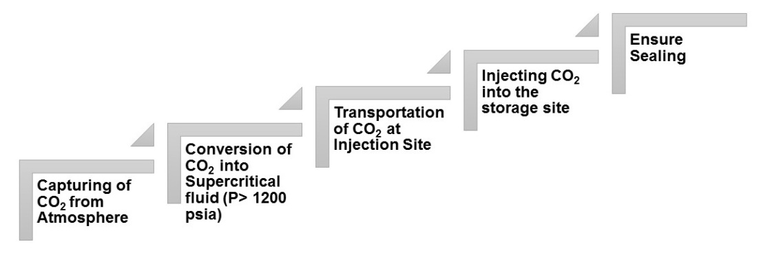
To begin with the whole CCS process, the first stage is to capture CO2 in the atmosphere by three main approaches power plants or large-scale industrial facilities. The three main technologies used in the capture process are post- combustion, precombustion and oxyfuel combustion capture [13]. After capturing CO2 through CCS technology, it undergoes pressurization and transforms into a liquid- like state referred to as supercritical CO2. Subsequently, it is conveyed through pipelines and injected into rocks located in formations deep beneath the Earth’s surface, a procedure known as geological sequestration [14].
Depleted oil and gas reservoirs present promising opportunities for CO2 sequestration due to several factors. There are extensive geological and subsurface data gathered over decades aids in characterizing the subsurface effectively [15]. Also, there are available infrastructures to make this process easier as compared to the other sequestration processes. However, an abandoned natural gas field stands out as a geologic reservoir with substantial potential for CO2 sequestration. The entire void volume of these abandoned gas fields could be utilized for CO2 storage. This is primarily because the typical exploitation of a gas field results in the extraction of between 80% to 90% of the available gas [16]. Also, in a depleted gas field, a substantial portion of the pore space may often be suitable for CO2 storage. This is attributed to the fact that in many gas fields, minimal water invasion occurs during production. Following the cessation of production from such fields, the pore space is filled with low-pressure methane, which possesses high compressibility. Consequently, a considerable proportion of the pore space becomes available for the injection and occupation of CO2 [17]. CO2 sequestered will leak out to the atmosphere if no sealing mechanism exists [18]. The figure below illustrates the step-by-step procedure of CO2 sequestration in the depleted hydrocarbon reservoirs (Figure 3).
Mechanisms of Storage
CO2 geological storage is feasible in a range of geological environments located within sedimentary basins which depleted oil and gas fields are viable options for storing CO2 [9]. CO2 is sequestered in geological formations through various trapping mechanisms, the specific mechanism being contingent on the type of formation [19]. A supercritical fluid is a substance that displays characteristics of a gas and liquid simultaneously. Such fluids possess surface tensions and viscosities akin to those of gases, along with densities comparable to liquids [20]. When supercritical CO2 is injected into DOGR, it exhibits three kinds of storage mechanisms. Below are the various mechanisms discussed. Structural Trapping: Involves the physical confinement of CO2 within a reservoir due to the geological structure of the formation. Reservoir rocks often have natural traps, such as anticlines or faulted structures, which can prevent the upward migration of CO2. The caprock, an impermeable layer above the reservoir, further seals and contains the stored CO2, ensuring its confinement over time. This mechanism relies on the natural geological features of the reservoir to securely trap the CO2 [21]. Solubility Trapping: Here, the dissolution of CO2 in the formation water within the reservoir rock. As CO2 dissolves into the water, it forms a dissolved phase that is less mobile and prone to migration. This dissolved CO2 can remain in the reservoir for an extended period, contributing to long-term storage stability. Solubility trapping complements the other mechanisms by providing an additional means of retaining CO2 within the reservoir, enhancing the overall security of the storage process [22]. Mineral Trapping: In this process, CO2 reacts with minerals in the rock formation to form stable carbonates or other mineral compounds. This mineralization locks the carbon in a solid state, providing a secure and permanent form of storage [23].
In combination, these trapping mechanisms work synergistically to ensure the effective and secure storage of CO2 in Depleted Oil and Gas Reservoirs (DOGR). The success of CO2 storage in DOGR relies on a comprehensive understanding and optimization of these mechanisms to mitigate environmental impact and contribute to sustainable carbon sequestration efforts.
Feasibility of Storage Option
The geological sequestration of CO2 could be technically viable in diverse reservoir settings, encompassing abandoned oil and gas fields, saline aquifers, deep coal seams, and sub-seabed strata. While each of these approaches shows promise for efficient sequestration under specific surface and sub-surface conditions, storing CO2 in depleted oil and gas fields presents notable comparative advantages [24].
Furthermore, the characteristics of depleted oil and gas reservoirs, shaped by their prior use for hydrocarbon storage, often render them conducive to efficient CO2 sequestration [15]. The presence of structural or stratigraphic traps, which initially trapped oil and gas, can serve as secure storage zones for injected CO2, minimizing the risk of leakage or unintended migration. The reservoir’s well-defined boundaries contribute to containment, providing a natural and robust framework for CO2 storage. Additionally, the compressibility of low-pressure methane, typically left behind in the reservoir after hydrocarbon extraction, especially for abandoned gas reservoirs, results in a substantial volume of pore space. This compressibility allows for a higher proportion of the reservoir’s pore space to be effectively occupied by injected CO2, maximizing storage capacity [17].
Methodology
This research’s methodology chapter serves as a foundational pillar on which the assessment of CO2 storage potential in depleted reservoirs within the Ship Shoal region of Louisiana is built. It delineates the systematic framework employed to conduct a thorough and rigorous analysis, guiding the reader through the intricate steps undertaken to achieve the research objectives. As such, this introductory section provides insight into the criteria for block search and selection, the significance of each step in clarifying the CO2 storage landscape within the study area, the main approach adopted for CO2 storage capacity estimation, and the rationale behind methodological choices.
This chapter shows how the research was done to study CO2 storage in depleted reservoirs in the Ship Shoal area. It highlights our commitment to doing the research well and making sure our findings are accurate. A mix of careful methods, smart analysis, and scientific investigation to understand how CO2 storage works in this region were used. By doing this, we hope to learn more about the geological, engineering, and environmental aspects of CO2 storage in depleted reservoirs.
Focus Area
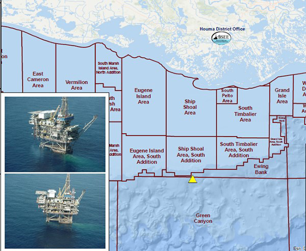
This research work involves some depleted oil and gas reservoirs in the Ship Shoal area of the Gulf of Mexico mostly in the state of Louisiana. Ship Shoal is a prominent geological formation known for its significance in the oil and gas industry and its potential for carbon CCS initiatives. Situated approximately twenty miles off the coast of Louisiana, Ship Shoal encompasses a series of submerged sand ridges and shoals that have long been exploited for their hydrocarbon reserves. The area is characterized by a history of oil and gas exploration and production, with numerous wells drilled into the reservoirs beneath the seabed. Many of these wells have since been depleted or abandoned, meaning that the recoverable hydrocarbons have been largely extracted, leaving behind voids or depleted reservoirs [25].
The geology of Ship Shoal can be attributed to its formation through various geological processes over millions of years. The area was once a shallow marine environment, characterized by the deposition of sediments such as sand, silt, and clay. Over time, these sediments accumulated and underwent compaction and lithification, transforming into sedimentary rocks. One of the key geological features of Ship Shoal is its presence of structural traps and stratigraphic traps. These structural features create reservoirs where hydrocarbons can accumulate, trapped by impermeable layers of rock above.
Additionally, Ship Shoal exhibits stratigraphic traps, which occur when variations in the sedimentary rock layers create conditions conducive to hydrocarbon accumulation. For example, changes in porosity and permeability within the sedimentary sequence can create reservoirs where hydrocarbons migrate and become trapped.
In recent years, there has been growing interest in repurposing depleted oil and gas wells for CO2 storage as part of efforts to mitigate greenhouse gas emissions and combat climate change. Ship Shoal presents a promising opportunity for CCS projects due to its geological characteristics, established infrastructure, and proximity to industrial sources of CO2 emissions along the Louisiana coast (Figure 4).
The study area in Ship Shoal offers a unique opportunity to assess the feasibility and potential benefits of CO2 storage in depleted oil and gas wells. Researchers and industry stakeholders are investigating various aspects of CO2 sequestration in this area, including reservoir characteristics, CO2 injection and storage mechanisms, subsurface fluid dynamics, and potential environmental impacts.
We will focus on estimating the CO2 storage potential in specific blocks within the Ship Shoal area. These blocks are SS028, SS032, SS037, SS056, SS058, and SS072. Note that SS028, SS032, and SS037 are laterally contiguous, covering 51,244.82 acres (about twice the area of Manhattan). Similarly, SS056 and SS058 are also adjacent, encompassing a combined area of 28,750.1 acres. Additionally, SS072 has an area of 27,596.22 acres. This detailed delineation of the blocks allows for a comprehensive assessment of CO2 storage potential across distinct areas within the Ship Shoal region, ensuring a thorough understanding of the geological and reservoir characteristics that influence storage capacity.
Block Search and Selection Criteria
For the selection of well sites, the criteria are based on guidelines outlined in the BOEM (Bureau of Ocean Energy Management) report concerning the identification of Tier Depleted Reservoirs in the Gulf of Mexico [26]. In this process, the two main criteria considered are as follows:
Site Criteria - Petroleum Exploration Approach
- Priority was given to blocks located within a specific distance from the federal-state boundary, with a preference for blocks within twenty-five miles from the shoreline as shown in Figure 5 below.
- Also, blocks in water depths of less than one hundred feet are of great interest (Figure 6).
These criteria align with the petroleum exploration approach, aiming to optimize the accessibility and feasibility of well sites for further study and potential CO2 storage initiatives.
![Figure 5: Distance buffers from the federal-state boundary [26].](/fulltextimages/12789/fig_5.png)
![Figure 6: Water depths below one hundred feet [26].](/fulltextimages/12789/fig_6.png)
Reservoir Criteria–Petroleum System Approach • The selection process also considered the reservoir characteristics, particularly focusing on the petroleum system approach.
- Reservoirs with proven confining systems, indicating their ability to effectively contain stored CO2 without leakage or migration.
- Furthermore, reservoirs located at specific depths and pressures conducive to the stable storage of supercritical CO2 are given priority. In this regard, reservoirs within the depth range of 3000 feet to 10,000 feet (about 3.05 km) are best for providing a suitable environment for CO2 storage.
In summary, the choice of well blocks is based on a combination of criteria aimed at maximizing the potential for successful CO2 storage initiatives. By considering both site and reservoir characteristics, the chosen wells will offer favorable conditions for further investigation and assessment of CO2 storage potential within the Ship Shoal area.
Storage Capacity Estimates
US Department of Energy Method: The methodology established by the US Department of Energy (US-DOE) outlines how to estimate CO2 storage resources based on the volume of pore spaces in the oil or gas reservoirs. These reservoirs have historically contained naturally occurring deposits of oil or gas. and are potentially viable options for storing CO2 in the future [27]. The methodology for estimating storage volume in depleted oil and gas fields involved assessing the volume of oil and gas that has been or could be extracted. It was assumed that this volume could be replaced by an equivalent volume of CO2. However, it is important to note that there is not always a direct correlation between the volume of oil and gas present and the capacity of the reservoir to contain hydrocarbons [28]. The typical format of the volumetric equation used to estimate the mass of CO2 storage resources (MCO2) for geological storage in oil and gas reservoirs is as follows:
( ) 2 2 / 1 CO n e wi CO oil gas M Ah S B E ϕ ρ = − (1)
The result of multiplying the area (A), net thickness (hn), average effective porosity (ɸe), original hydrocarbon saturation (1-Swi), and the initial oil or gas formation volume factor (B) yields the Original Oil in Place (OOIP) or Original Gas in Place (OGIP), volume Goodman A, et al. [27]. The values for these variables were obtained from the Bureau of Ocean Energy Management (BOEM) Data Center [29]. To translate the volume to the mass of CO2 that can be stored, the volume estimated is multiplied by the density of supercritical CO2 (ρCO2) under the said reservoir conditions that can be injected into the depleted oil/gas reservoir. To estimate these densities at the specific reservoir temperatures and pressures, the works on physical properties of CO2 supercritical by Pan B, et al. [30] were used. A pressure- density graph of supercritical CO2 is used to determine the densities of CO2 at varying reservoir temperatures and pressures (Figure 7).
![Figure 7: Pressure-density graph of CO2 supercritical at varying temperatures by Pan B, et al. [30].](/fulltextimages/12789/fig_7.png)
The storage efficiency factor (Eoil/gas) represents the proportion of pore space within the storage reservoir that is effectively available for CO2 trapping and retention over time. In the context of estimating CO2 storage capacity, the storage efficiency factor accounts for various factors that can affect the effectiveness of CO2 storage, such as reservoir heterogeneity, trapping mechanisms, and potential leakage pathways. It essentially adjusts the total pore volume of the reservoir to reflect the portion that can effectively trap and retain CO2. To obtain the Eoil/gas, the scatter plot in Figure 8 shown below for various reservoir types (oil, gas, or combination) was used based on the hydrocarbon recovery factor (HCRF) [31].
![Figure 8: The figure compares the CO2 Storage Efficiency Factor (Eoil/gas) calculated with the Department of Energy (DOE) equation to the hydrocarbon recovery factor (HCRF) for modelled gas, oil, and combined reservoirs by Agartan E, et al. [31].](/fulltextimages/12789/fig_8.png)
CSLF Approach: The Carbon Sequestration Leadership Forum (CSLF) method was also used to estimate the CO2 sequestration potential of the selected Ship Shoel blocks. This approach provides a structured framework for evaluating the potential for CO2 storage in depleted oil and gas reservoirs, drawing upon production data and geological parameters [32]. By leveraging the CSLF approach, a robust estimation of CO2 storage capacity, informed by industry best practices and international standards is made possible. CO2 storage estimates derived from production data are typically favored over those based on volumetric assessments. This preference stems from the detailed information extracted directly from the formation through production activities. However, in cases where production data are unavailable, volumetric-based estimates of CO2 storage resources may be utilized as an alternative approach [27]. The following equation, based on production data, is used to estimate CO2 storage resources for gas (2) and oil (3) reservoirs.
PZ T M R F OGIP P Z T ρ = −
( ) 2 2 1 r (2)
s r r CO CO f IG r s s R OOIP M V V B ρ = − +
(3) f CO CO iw pw f
2 2r ρco2r represents the density of supercritical CO2 (lb per cf) at the reservoir which has been discussed in the DOE method of estimating potential storage capacity. In the provided equations above, OGIP represents the initial volume of gas in place, while OOIP represents the initial volume of oil in place. Rf signifies the recovery factor, and FIG represents the fraction of injected gas. P, T, and Z denote pressure (psi), temperature (F), and gas compressibility factor, respectively. In equation (2), the subscripts “r” and “s” indicate reservoir and surface conditions, respectively. The pressure and temperature of supercritical CO2 at surface conditions are 1070 psi and 87°F respectively. These are known for the pressure and temperature at which CO2 reaches the supercritical state [33]. The Gas compressibility factor, Z was estimated using the Brill-Beggs-Z correlation found in the Excel companion worksheet of the Petroleum Production Engineering book [34]. Bf is the formation volume factor used to adjust oil volume from standard conditions to in-situ conditions. Viw and Vpw in cubic feet denote the volumes of injected and produced water, in corresponding order, which is relevant in the context of oil reservoirs and estimated based on production records. Data on OGIP, OOIP, Rf, and Bf were sourced from the BOEM Data Center [29], while information on FIG, Viw, and Vpw was collected through the Offshore Well Lease 7 Database. These parameters collectively provide insights into reservoir characteristics and fluid behavior essential for the analysis and interpretation of the study’s findings.
Agartan Approach: The Agartan study introduced a correlation designed to assess the potential for CO2 storage in various types of reservoirs (including oil, gas, or mixed). This correlation is based on the cumulative production of reservoir fluids (oil, free gas, and water). By applying this correlation, one can estimate the volume of CO2 that a reservoir can store. Multiplying this estimated volume by the density of CO2 at reservoir conditions (i.e., pressure and temperature) provides an estimate of the mass of CO2 that could potentially be stored in depleted oil and gas reservoirs [31]. Below are the equations representing the three types of reservoirs:
• Oil reservoir:
2 0.2619 CO V Cumulative production = × (4)
• Gas reservoir:
2 0.4299 CO V Cumulative production = × (5)
• Combination reservoir (oil and gas):
2 0.3397 CO V Cumulative production = × (6)
Exemplary Study
This study focuses on estimating the CO2 sequestration potential in six distinct blocks within the Ship Shoal area of the Gulf of Mexico (SS028, SS032, SS037, SS056, SS058, and SS072). The study will utilize established formulas from the DOE and the Carbon Sequestration Leadership Forum (CSLF) to assess the feasibility of CO2 storage in these offshore reservoirs. Data sourced from the Bureau of Ocean Energy Management (BOEM) Data Center and the Offshore Well Lease 7 (OWL) database form the basis for this analysis. The table below shows details of the blocks that were studied (Table 1).
| Block name | Total area, acres. | Sand Type |
|---|---|---|
| SS028 | 23,119.72 | Gas |
| SS032 | 18,750.07 | Oil, Gas & Combination |
| SS037 | 9,375.03 | Predominantly gas with pockets of oil |
| SS056 | 5,000.01 | Gas |
| SS058 | 23,750.09 | Oil, Gas & Combination |
| SS072 | 27,596.22 | Oil (few), Gas & Combination |
Table 1: A summary of the various blocks in the Ship Shoal that were studied.
Results and Discussions
The study focused on estimating the potential storage capacity for CO2 in six blocks situated in Ship Shoal in the Gulf of Mexico (SS028, SS032, SS037, SS056, SS058, and SS072) using methodologies from both the US DOE, CSLF and the Agartan correlation. The total wells are sixty-six.
DOE Method of Estimating Potential CO2 Storage Capacity
For the DOE method, the estimation process incorporated various input parameters on the geological characteristics of the reservoirs. The CO2 storage efficiency factor, which is a function of the HCRF based on Agartan, et al. [31] plot yielded the following results as shown in Tables 2-6 and 7. For block SS056, which has just one well under study, the HCRF and the Eoil/gas are 0.53 and 0.72 respectively.
| SS028 | |
|---|---|
| HCRF | Eoil/gas |
| 0.78042 | 0.85357 |
| 0.60524 | 0.81708 |
| 0.6344 | 0.85644 |
| 0.44252 | 0.5974 |
| 0.51138 | 0.69036 |
| 0.27648 | 0.37324 |
| 0.51798 | 0.69927 |
| 0.7271 | 0.98159 |
| 0.12884 | 0.17393 |
| 0.15049 | 0.20316 |
| 0.76387 | 0.83123 |
| 0.47343 | 0.63913 |
| 0.57472 | 0.77588 |
| SS032 | |
| HCRF | Eoil/gas |
| 0.510046 | 0.68856163 |
| 0.4953 | 0.66865535 |
| 0.167622 | 0.22628914 |
| 0.053192 | 0.07180865 |
| 0.004945 | 0.00667536 |
| 0.054476 | 0.07354219 |
| 0.035408 | 0.04780129 |
| 0.517027 | 0.69798602 |
| 0.004092 | 0.00552372 |
| 0.000377 | 0.00050909 |
| 0.087368 | 0.11794747 |
Table 2: Values for HCRF and the storage efficiency factor for block SS028.
The provided results outline the storage efficiency factor (HCRF) for a series of scenarios, where the efficiency of CO2 storage is evaluated concerning the cumulative production of oil and gas (Eoil/gas). Each pair of values represents a specific instance or condition within the study.
Upon examination, the storage efficiency factor is considerably variable across different scenarios. For instance, HCRF values range from as low as approximately 0.13 to as high as nearly 0.98 for block SS028 and SS032 has between 0.0004 and 0.52. This wide range underscores the influence of various factors on the efficiency of CO2 storage within oil and gas reservoirs.
Several trends can be observed within the dataset. Firstly, there appears to be a positive correlation between cumulative production and the storage efficiency factor. In general, scenarios with higher cumulative production tend to exhibit higher efficiency factors, indicating that reservoirs with more extensive production histories may offer greater potential for CO2 storage.
| SS037 | |
|---|---|
| HCRF | Eoil/gas |
| 0.616434 | 0.832186 |
| 0.683078 | 0.922155 |
| 0.629374 | 0.849655 |
| 0.241041 | 0.325406 |
| 0.765643 | 0.964732 |
Table 3: Figures representing the HCRF and the storage efficiency factor in Block SS037.
| SS058 | |
|---|---|
| HCRF | Eoil/gas |
| 0.501844 | 0.677489 |
| 0.442177 | 0.596939 |
| 0.322189 | 0.434955 |
| 0.366929 | 0.495355 |
| 0.62961 | 0.849974 |
| 0.104499 | 0.141074 |
Table 4: Figures representing the HCRF and the storage efficiency factor in Block SS058.
The data for blocks SS037 and SS058 of Ship Shoal reveals a range of storage efficiency factors (HCRF) alongside cumulative production of oil and gas (Eoil/gas). Notably, the efficiency factors vary between approximately 0.24 and 0.96 for block SS037 and between 0.14 to 0.85 for block SS058, indicating differing levels of CO2 storage efficiency within this block.
Examining the relationship between cumulative production and HCRF, there seems to be a mixed pattern. While some scenarios demonstrate a positive correlation, with higher cumulative production associated with higher efficiency factors, others do not follow this trend.
This suggests that factors beyond cumulative production, such as reservoir heterogeneity and injection strategies, significantly influence CO2 storage efficiency in this block.
| SS072 | |
|---|---|
| HCRF | Eoil/gas |
| 0.17722 | 0.2392473 |
| 0.3799 | 0.51286411 |
| 0.04509 | 0.06087413 |
| 0.30497 | 0.41170648 |
| 0.1974 | 0.26649122 |
| 0.22086 | 0.29816537 |
| 0.50376 | 0.68007592 |
| 0.15011 | 0.20264989 |
| 0.42573 | 0.62473018 |
| 0.09724 | 0.13126795 |
| 0.61923 | 0.7359663 |
| 0.26259 | 0.35450202 |
| 0.46237 | 0.62420279 |
| 0.50481 | 0.68149822 |
| 0.19995 | 0.26993202 |
| 0.6473 | 0.87386081 |
| 0.2758 | 0.37232522 |
| 0.19314 | 0.26073745 |
| 0.20612 | 0.27826546 |
| 0.13293 | 0.17945469 |
| 0.3566 | 0.48140287 |
| 0.34304 | 0.46310818 |
| 0.2803 | 0.37841021 |
| 0.78048 | 0.85365324 |
| 0.53419 | 0.72115278 |
Table 5: Data about the HCRF and the efficiency factor for storing CO2 in Block SS072.
The calculated potential for CO2 sequestration presents a significant step towards understanding the feasibility of implementing CCS initiatives in the region. A comprehensive analysis of the data reveals the following estimates for CO2 storage capacity in each of the six blocks.
| DOE | |||
|---|---|---|---|
| Block name | MCO , gas 2 | MCO , oil 2 | Total |
| SS028 | 75,836,621 | - | 75,836,621 |
| SS032 | 6,684,229 | 454,804,835 | 461,489,065 |
| SS037 | 14,078,304 | 31,933,388 | 46,011,692 |
| SS056 | 5,908,312 | - | 5,908,312 |
| SS058 | 16,442,899 | 517,032,011 | 533,474,910 |
| SS072 | 145,748,086 | 7,751,055,669 | 7,896,803,756 |
| Total in lb. | 9,019,524,356 | ||
| Total in tons | 4,509,762 | ||
| CSLF | |||
| Block name | MCO , gas 2 | MCO , oil 2 | Total |
| SS028 | 57,724,189 | - | 57,724,189 |
| SS032 | 6,957,970 | 1,872,346,960 | 1,879,304,930 |
| SS037 | 10,136,923 | 139,817,973 | 149,954,897 |
| SS056 | 2,279,610 | - | 2,279,610 |
| SS058 | 8,129,531 | 1,069,702,220 | 1,077,831,751 |
| SS072 | 73,763,285 | 7,037,201,871 | 7,110,965,157 |
| Total in lb. | 10,278,060,536 | ||
| Total in tons | 5,139,030 |
Table 6: Summary potential CO2 storage estimate using the DOE’s method.
These results provide important discovery into the potential for CO2 sequestration in this Ship Shoal area, offering a foundation for further exploration and decision- making in the realm of carbon management strategies.
CSLF Method
In this section, we present the findings derived from the CSLF methodology, offering a nuanced understanding of the CO2 storage landscape in Ship Shoal. Through comprehensive data gathering, we delineate the spatial distribution of potential storage sites, assess storage capacities, and identify key factors influencing storage viability. These results serve as a foundation for informed decision-making and strategic planning in the pursuit of sustainable carbon management solutions.
A critical aspect of the process of estimating the potential storage capacity in depleted oil and gas reservoirs involves determining the gas compressibility factor. This essential parameter was accurately assessed across a spectrum of reservoir conditions encompassing varying temperatures and pressures using the Brill-Beggs Z correlation from the Excel spreadsheet companion found in the Petroleum Production Engineering book [34]. The results will be shown in the appendix.
After applying the CSLF method to assess the potential for CO2 storage in exhausted oil and gas reservoirs, the findings for the six blocks in Ship Shoal are outlined below (Table 8):
Agartan’s Correlation
The data provided offers a glimpse into the estimated CO2 storage capacities across different blocks within Ship Shoal, utilizing Agartan’s correlation. The total estimated CO2 storage capacity for the blocks under study is approximately 10.76 billion pounds or 5.38 million tons. This aggregate capacity presents a substantial reservoir for potential carbon capture and storage initiatives within the Ship Shoal region.
While SS072 emerges as the block with the highest estimated CO2 storage capacity, contributing approximately 6.98 billion pounds, it’s crucial to note the significance of other blocks as well. SS028, SS032, SS058, and SS037 also exhibit considerable storage capacities, contributing significantly to the overall potential for CO2 storage within Ship Shoal (Table 9).
| Block Name | MCO 2 |
|---|---|
| SS028 | 1,557,162,646 |
| SS032 | 954,409,108 |
| SS037 | 285,173,462 |
| SS056 | 115,843,388 |
| SS058 | 869,306,105 |
| SS072 | 6,977,904,323 |
| Total, lb | 10,759,799,032 |
| Total, ton | 5,379,900 |
Table 8: Summary potential CO2 storage estimate using the CSLF’s method.
Interestingly, the distribution of estimated CO2 storage capacities across different blocks reflects the complex interplay of geological, reservoir, and operational factors within the region. Variations in storage capacities among blocks underscore the importance of site-specific assessments and tailored CCS strategies to maximize storage potential effectively.
The results of the study provide useful perspectives into the potential for CO2 storage within specific blocks in the Ship Shoal in the GOM region. By utilizing both the DOE method and the CSLF equation, the study estimated significant CO2 storage potential within the selected blocks.
Considering DOE methodology, one key parameter considered in the analysis is the storage efficiency factor, which represents the proportion of pore space within the storage reservoir that is effectively available for CO2 trapping and retention over time. Accounting for this factor is crucial as it ensures a more accurate estimation of the actual CO2 storage capacity within the reservoir.
The study found that the combined potential storage capacity of the six selected blocks, after adjusting for the storage efficiency factor, is approximately 4,509,762 tons of CO2 using the DOE method and 5,139,030 tons of CO2 using the CSLF equation. These results underscore the significant potential for CO2 storage within the GOM (Ship Shoal to be specific), which is of paramount importance for mitigating greenhouse gas emissions and addressing climate change concerns (Table 10).
| Method | DOE | CSLF | Agartan |
|---|---|---|---|
| Total CO Storage 2 Estimate (tons) | 4,509,762 | 5,139,030 | 5,379,900 |
Table 7: Total Estimates of CO2 Storage (in tons) Generated by Different Methods: DOE, CSLF, and Agartan.
The CSLF method and Agartan correlation yield close estimates of 5,139,030 and 5,379,900 tons, respectively, for CO2 storage potential because they rely on production data that contributes to their similarity. In contrast, the DOE method yields a notably different estimate of 4,509,762 tons, as it relies on volumetric calculations.
Conclusion
This research investigated the potential for CO2 sequestration in depleted oil and gas reservoirs across six blocks (SS028, SS032, SS037, SS056, SS058, and SS072) in the Ship Shoal field, Gulf of Mexico. Three different methods were employed to estimate the CO2 storage capacity: the DOE method, the CSLF approach, and the Agartan correlation.
The DOE method yielded an estimated potential storage capacity of 4,509,763 tons of CO2 for the studied blocks. The CSLF approach, which utilizes production data and geological parameters, estimated a slightly higher capacity of 5,139,030 tons of CO2. The Agartan correlation, based on the relationship between cumulative production and storage efficiency factors, yielded the highest estimate of 5,379,900 tons of CO2 storage potential.
While the estimates vary across the three methods, the findings consistently indicate significant CO2 storage potential within the studied blocks. Notably, block SS072 emerged as the block with the highest estimated capacity, contributing approximately 6.98 billion pounds (3.49 million tons) according to the Agartan correlation.
It is crucial to highlight that this analysis focused solely on six blocks within the Ship Shoal field. Considering the vast number of potential storage sites in the Gulf of Mexico region, the overall CO2 storage capacity could be substantially higher when all suitable depleted reservoirs are evaluated.
The research findings contribute to the assessment of depleted oil and gas reservoirs as viable options for CO2 sequestration, addressing the pressing need for atmospheric CO2 reduction and mitigating the impacts of greenhouse gas emissions.
Limitations
A limitation of employing the CSLF method in estimating CO2 storage potential is the assumption of standardized surface pressure and temperature conditions for CO2 injection. This method relies on predefined minimum values for CO2 to transition into its supercritical state (1070 psi and 87°F). However, actual site-specific conditions may vary, impacting the accuracy of storage capacity estimations. This limitation underscores the need for further refinement and adaptation of modelling approaches to account for variations in surface conditions encountered in different geological settings.
With regards to the DOE’s method for estimating CO2 storage capacity in depleted oil and gas reservoirs, one observed limitation is its reliance on simplified assumptions about reservoir characteristics. This estimation method typically assumes homogeneous reservoir properties which may not be the case as reservoirs often exhibit heterogeneity in net thickness, connate water saturation and porosity.
Also, the fraction of injected gas for individual sands, an input variable, is unknown; the fraction of injected gas for the entire block was utilized as a representative value for the individual sands.
Recommendations
One recommendation for this work is to conduct further research to assess CO2 storage potential in additional blocks within the Gulf of Mexico region. This would help to expand the understanding of CO2 storage opportunities and enhance the accuracy of overall estimates. Additionally, ongoing collaboration between government agencies, industry stakeholders, and research institutions is crucial to advance CCS technologies and address technical and regulatory challenges associated with CO2 storage initiatives.
In embarking on any CO2 injection projects in depleted oil and gas reservoirs, risk factors such as legacy wells and previous hydraulic fracturing must be noted and carefully researched.
Conflicts of Interest
The corresponding author, on behalf of all co-authors, affirms that there are no conflicts of interest to disclose.
References
-
Exxon Mobil Corporation (2009) Outlook for Energy A View to 2030.
-
United States Environmental Protection Agency (2023) Overview of Greenhouse Gases.
-
NOAA (2023) Annual 2023 Global Climate Report.
-
IEA (2022) World energy outlook.
-
Friedlingstein P, O’Sullivan M, Jones MW, Andrew RM, Bakker DE, et al. (2023) Global Carbon Budget 2023. Earth System Science Data 15(12): 5301-5369.
-
Energy Agency I (2023) Global Energy and Climate Model Documentation.
-
Matthew R (2016) Record-Breaking Climate Trends Briefing.
-
UNFCCC (2024) Key aspects of the Paris Agreement.
-
IPCC (2005) Carbon dioxide capture and storage.
-
Energy Agency I (2021) Global Energy Review: CO2 Emissions in 2021 Global emissions rebound sharply to highest ever level.
-
EPA U (2023) Inventory of US Greenhouse Gas Emissions and Sinks.
-
UNEP (2022) How do greenhouse gases actually warm the planet?
-
CRS (2022) Carbon Capture and Sequestration (CCS) in the United States.
-
Drax Global (2022) How do you store CO2 and what happens to it when you do?
-
Zoback MD, Gorelick SM (2012) Earthquake triggering and large-scale geologic storage of carbon dioxide. In Proceedings of the National Academy of Sciences of the United States of America 109 (26): 10164-10168.
-
Muggeridge A, Cockin A, Webb K, Frampton H, Collins I, et al. (2014) Recovery rates, enhanced oil recovery and technological limits. In Philosophical Transactions of the Royal Society A: Mathematical, Physical and Engineering Sciences 372(2006): 1-25.
-
Holloway (1996) An overview of the underground disposal of carbon dioxide.
-
Gupta A (2010) SPE 135595 Capacity and Constraints for Carbon Dioxide Sequestration in Aquifers and Depleted Oil/Gas Reservoirs in Carbonate Environment. SPE- 135595-MS.
-
Heddle G, Herzog H, Klett M (2003) The Economics of CO2 Storage.
-
Corrosionpedia (2018) Supercritical Carbon Dioxide.
-
US Department of Energy (1999) Carbon Sequestration Research and Development.
-
Herzog HJ (2001) What future for carbon capture and sequestration? Environmental Science and Technology: 148A-153A.
-
Faruk C (2007) Reservoir Formation Damage. 2nd(Edn.), Gulf Professional Publishing.
-
Iea GHG (2000) Barriers to overcome in implementation of CO2 capture and storage storage in disused oil and gas fields Title: Barriers to overcome in implementation of CO2 capture and storage-Storage in disused oil and gas fields Reference number: PH3/22 Background to the Study.
-
Bruno MS (2018) Assessment of CO2 Storage Resources in Depleted Oil and Gas Fields in the Ship Shoal Area. Gulf of Mexico Final Report.
-
Alonso C, Boudreau L, Cross K, Keevan J, Stephens B, et al. Identification of Tier 1 Depleted Reservoirs in the Gulf of Mexico BOEM Gulf of Mexico Region Resource Evaluation Slide.
-
Goodman A, Hakala A, Bromhal G, Deel D, Rodosta T, et al. (2011) U.S. DOE methodology for the development of geologic storage potential for carbon dioxide at the national and regional scale. International Journal of Greenhouse Gas Control 5(4): 952-965.
-
Nicot JP, Hovorka SD (2009) Leakage pathways from potential CO2 storage sites and importance of open traps: case of the Texas Gulf Coast. AAPG Studies in Geology 321-334.
-
(2024) Bureau of Ocean Energy Management. Data Center.
-
Pan B, Lei J, Zhang L, Guo Y (2017) Research on the physical properties of supercritical CO2 and the log evaluation of CO2-bearing volcanic reservoirs. Journal of Geophysics and Engineering 14(5).
-
Agartan E, Gaddipati M, Yip Y, Savage B, Ozgen C (2018) CO2 storage in depleted oil and gas fields in the Gulf of Mexico. International Journal of Greenhouse Gas Control 72: 38-48.
-
Mckee BN (2008) Technical Group Task Force for Review and Identification of Standards for CO2 Storage Capacity Estimation Phase III Final Report. Task Force for Review and Identification of Standards for CO2 Storage Capacity Estimation Phase III Final Report Decision Document.
-
Knaust S, Andersson M, Rogeman N, Hjort K, Amberg G, et al. (2015) Influence of flow rate, temperature and pressure on multiphase flows of supercritical carbon dioxide and water using multivariate partial least square regression. Journal of Micromechanics and Microengineering 25(10).
-
Boyun G, Xinghui L, Xuehao T (2017) Petroleum Production Engineering, 2nd(Edn.), Gulf Professional Publishing.
- Nigeria’s Vulnerability in the Face of Global Energy Policy
- A Simulation Study of Investigation of Optimum Oil Production Performance by Applying Various Gas Injection Methods in Oil Reservoir
- Characterization of Permo-Triassic Reservoirs through Thermal Maturity Assessment of Westphalian Source Rocks in the Cheshire Basin
- Influence of Microwax on the Rheological and Thermal Behaviour of a Wax Crude Oil
- Real-Time Monitoring and Performance Optimization of Steam Injection in Heavy Oil Reservoirs Using Fiber Optic Sensing and Integrated Predictive Simulation Models
- Rapid On-Site Determination of the Total Petroleum Hydrocarbon Content of Soils by Handheld Fourier Transform Near-Infrared Spectroscopy: Development of a Global, Site- and Scanner- Independent Calibration Model