Comments and Protocols for the Construction and Calibration of Ag AgCl Reference Electrodes
Despite the vital importance of reference electrodes, RE, it is common for PhD students in electrochemistry and other users of electrochemical instruments to lack a thorough understanding of their creation and calibration. This work presents the protocol to construct Ag/AgCl RE with different NaCl concentrations. The experimental RE potentials are measured using two techniques and compared to those obtained using the Nernst equation. The RE potential similarities or differences observed when different NaCl concentrations are present are also discussed. Furthermore, using an electrolytic cell to deposit AgCl onto the silver wire part of the RE and determining the mass of AgCl formed using Faraday’s law of electrolysis are presented. These reference electrodes are easily constructed, and the materials needed are readily available and non-toxic. Furthermore, the reference electrodes exhibit good potential stability as a function of time.
Introduction
Potential-controlled electrochemical methods (potentiostatic or potentiodynamic methods) are those in which the current passing in an electrochemical cell is measured as a function of the potential applied to the working electrode. Unfortunately, there is no way to measure this applied potential directly. As Kissinger and Bott have perfectly expressed, “…electrochemistry with a single electrode is like the sound of one hand clapping” [1]. All that can be measured are potential differences when two half-cells are connected. Therefore, the measurement of any applied potential to the working half-cell requires the potential of the second half-cell to be stable and reproducible over time and with temperature, presenting a well-defined activity value. This is achieved in practice by placing a second electrode, called the reference electrode, RE, in the cell and measuring the working electrode potential as the energy difference between the two electrodes. The half-cell potential of the RE serves then as the “reference point” along the potential axis by which we judge the oxidizing or reducing power of the working electrode in the vicinity of the interfacial region between the working electrode and the electrolytic solution. This means that the zero on the potential axis of an electrochemical experiment is just arbitrary.
Despite the vital importance of RE, it is common for PhD students in electrochemistry and other general users of electrochemical techniques (e.g., pH electrodes) to lack a thorough understanding of RE creation, reconditioning and calibration. Besides, a lack of knowledge of RE can lead to inaccurate results, severely affecting scientific research. Inaccurate results can stem from various sources, such as errors in the preparation of the reference electrode, electrode contamination, or changes in internal ion concentrations with time. These errors can lead to a shift in the RE potential, resulting in inaccurate potential measurements and, consequently, erroneous experimental data being reported.
The construction of RE as a practical activity can be found throughout the last 20 or 30 years of literature [2, 3, 4, 5, 6, 7, 8]. However, in general, all existing literature tries to propose simplistic construction approaches without explaining several key concepts and misconceptions, such as i) how the RE potential could be obtained theoretically (with the use of the activity coefficient in the Nernst equation) to verify or predict the practical results; and ii) the silver/silver chloride standard redox potential was not determined at 1M chloride concentration as reported in several books [9, 10], but under diluted conditions (vide infra). Therefore, the discussion and procedure presented in this work should help to understand the thermodynamic properties of Ag/AgCl RE, how an electrolytic cell can be used during the construction of RE and, more importantly, to integrate and clarify several compartmented and poorly explained concepts into a simple conceptual perception.
Critical Considerations
The Ag/AgCl reference electrode is the most used RE due to its simplicity, stability, inexpensive design, and non- toxic components. In addition, the simplicity of this electrode lends itself to microfabrication and incorporation into sensors, such as pH electrodes [11].
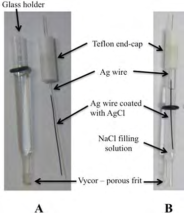
Figure 1 shows all parts of a silver/silver chloride RE, consisting of an Ag wire coated by a layer of AgCl and immersed into a chloride solution saturated with AgCl. This RE is in contact via a vycor frit to the external electrolyte solution in an electrochemical cell or storage container.
The controlling redox process is
( ) ( ) ( ) AgCl s e Ag s Cl aq − − + + (1)
Which under standard conditions [chemical activity for the relevant species (a) = 1 and temperature = 25 °C] has a standard reduction potential (E°) of 0.222 V vs. SHE [12, 13, 14, 15].
When a RE is built using this redox process, the potential of this electrode will be dependent on the chloride ion activity, , which generally differs from one (a ≠ 1). Under
non-standard conditions, the RE potential can be calculated using the Nernst equation:
RT E E Ina nF (2)
$$ E _ {A g / A g C l} = E _ {A g / A g C l} ^ {\theta} - \frac {R T}{n F} I n a _ {C l} $$ Where Ag AgCl E is the half-cell reduction potential (potential of the Ag/AgCl RE constructed) at the temperature of interest, Ag AgCl Eθ is the standard half-cell reduction potential (0.222 V vs. SHE), R is the universal gas constant: R
= 8.314472 J K−1 mol−1, T is the temperature in kelvins, and F
is the Faraday constant: F = 96,485.4 С mol−1. The
$$ a _ {C l ^ {-}} \mathrm {c a n} $$
be obtained from the nominal concentration of chloride, [Cl-],
by using the activity coefficient,
$$ \gamma_ {C I ^ {-}}: $$ $$ a _ {C l ^ {-}} = \gamma_ {C l ^ {-}} \left[ C l ^ {-} \right] \tag {3} $$
Inserting equation 3 into the Nernst equation (eq 2) ( ) Ag Ag Ag Cl Cl AgCl AgCl AgCl RT RT RT E E In Cl E In In Cl nF nF nF $$ E _ {A g} ^ {\theta} / _ {A g C l} - \frac {R T}{n F} I n \left(\gamma_ {C l ^ {-}} \left[ C l ^ {-} \right]\right) = E _ {A g} ^ {\theta} / _ {A g C l} - \frac {R T}{n F} I n \gamma_ {C l ^ {-}} - \frac {R T}{n F} I n \left[ C l ^ {-} \right] $$ (4) allows the calculation of the RE potential using concentration values. It is worth noting from this equation that when the molar concentration of chloride ions is unity, the Ag AgCl E is not equal to EAg AgCl θ
. This is due to the
1 Cl γ
−≅only at diluted
concentrations (below 0.02 M), being the
$$ \gamma_ {C l ^ {-}} = 0. 6 0, 0. 5 7 $$
and 0.57 for 1, 2 and 3 M chloride concentration, respectively
The construction of Ag/AgCl RE with different NaCl concentrations is presented below, where the experimental RE potential will be measured and compared to that obtained using the Nernst equation (Eq 4). Furthermore, using an electrolytic cell to deposit AgCl onto the silver wire part of the RE is presented, and the number of moles of AgCl formed by using Faraday’s law of electrolysis (Eq 5) is determined.
$$ Q = n F N \tag {5} $$
Where Q is the charge (in coulomb, C) passed in the circuit [being C the current, A, that flows through the circuit per second], n is the number of electrons transferred in the balanced equation, and N is the number of moles of product formed. It is worth mentioning that although this last calculation is not relevant to the construction of RE, it could be a formative activity for new research staff or laboratory students.
Materials and Methods
Reagents
Hydrochloric acid (HCl, 37%), ammonia solution (25%), sodium chloride (NaCl, ≥99%), and silver chloride (AgCl, >99%) were purchased from Sigma-Aldrich and used as received from the manufacturer.
Methods
This practical experiment can be performed in any general chemistry laboratory. Requirements are a glass holder with a cap and silver wire (Figure 1). Commercial holders and an Ag wire from ALS (Japan) were used in our laboratory. However, any plastic barrel with silver wire and porous frit can be used. Furthermore, an Interface1000 electrochemical workstation (Gamry, USA), a voltmeter with high input impedance, a platinum wire and a laboratory-standard Ag/AgCl, 3M NaCl (ALS, Japan) is used. This last RE has a potential of –0.034 V vs SCE and 0.207 V vs SHE at 22±1°C and should only be used for RE calibration (never used for an electrochemical experiment). This last requirement is essential to warrant stability in its redox potential.
Reference Electrode Preparation
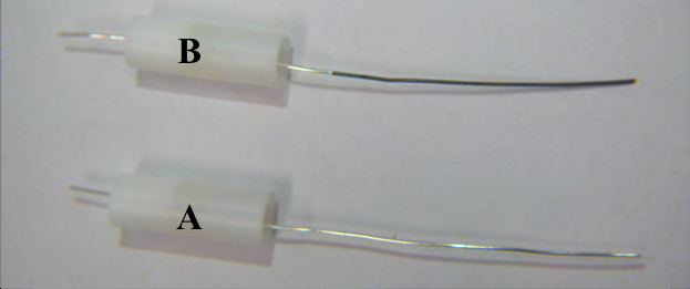
The silver wire is immersed in 25% ammonia solution for a few minutes and then rinsed thoroughly with deionized water. After this cleaning step, the silver wire is immersed into an electrochemical cell (electrolytic cell) containing 0.1 M HCl solution and connected to the potentiostat as the working electrode. A platinum wire is used as the reference and counter electrode in this cell. A chronocoulometry (or chronoamperometry followed by data integration) is then performed by applying a potential of 0.5 V for 30 min (the data of this experiment could be used to calculate the mass of AgCl formed). Then, the coated wire is washed with doubly distilled water. The colour of the AgCl-coated silver wire should be sepia (dark brown with a reddish tint) if chloridized in the absence of light or pale tan to brown if chloridized while exposed to a light source (Figure 2).
The AgCl-coated silver wire is then introduced into the RE glass holder (Figure 1) and placed into the storage recipient containing a NaCl solution, which concentration matches the internal RE solution.
Reference Electrode Calibration
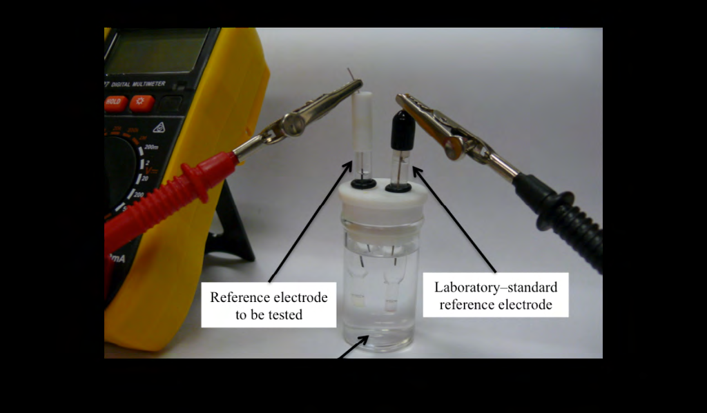
Two methods could be used to calibrate the RE potential. The first method involves placing the recently constructed (or the RE to be tested) and the laboratory-standard RE in an electrochemical cell containing the same solution as the internal RE solution. For instance, if the RE prepared is an Ag/AgCl, 2M NaCl, the electrochemical cell will contain a 2 M NaCl solution. This is important to minimize the presence of junction potentials. Subsequently, the RE potential is measured using a high-impedance voltmeter. It is worth mentioning here that this setup is equivalent to a galvanic cell (concentration cell), being each one of the REs the hemi- reactions and the 2 M NaCl solution in the electrochemical cell equivalent to the salt bridge.
The second method requires the same setup. However, the voltmeter is replaced by a potentiostat. In this case, the laboratory-standard RE is connected to the potentiostat reference terminal and the RE to tested to the potentiostat working terminals (this data will be used to calculate the potential of your reference electrode vs. the laboratory- standard reference electrode).
The measured potential with both techniques can be represented by the following equation (eq 6):
$$ E _ {R E _ {2}} = E _ {m e t e r} + E _ {R E _ {1}} \tag {6} $$
2 RE E is the potential of the RE constructed or tested, 1 RE E the potential of the laboratory-standard RE (Ag/ AgCl, 3M NaCl) vs. SHE, and meter E the potential value red from the voltmeter or the potentiostat.
Where
Results and Discussion
Electrode Preparation
An electrolytic cell is ensembled to deposit an AgCl layer onto the silver wire surface. The charge and/or current can be recorded as a function of time for 30 minutes and plotted as shown in Figure 3. This deposition can be performed with and without stirring, which, if performed by new research staff or students, provides the opportunity to understand how convection mass transfer (stirring or hydrodynamic transport) affects electrochemical experiments. It is worth emphasizing that the charge obtained in this experiment will depend on the silver wire area immersed in the 0.1 M HCl solution and the presence or absence of stirring. Therefore, a variation in the reported mass of AgCl formed between different electrodes is warranted. In the case presented in Figure 3, a charge Q = 1.21 C was obtained. Using equation 5 [considering n = 1 (Eq 1)] and the AgCl molar mass (143.32 g/mol), it is possible to determine that an AgCl mass of 1.80 mg is formed during this experiment.
![Figure 3: This deposition can be performed with and without stirring, which, if performed by new research staff or students, provides the opportunity to understand how convection mass transfer (stirring or hydrodynamic transport) affects electrochemical experiments. It is worth emphasizing that the charge obtained in this experiment will depend on the silver wire area immersed in the 0.1 M HCl solution and the presence or absence of stirring. Therefore, a variation in the reported mass of AgCl formed between different electrodes is warranted. In the case presented in Figure 3, a charge Q = 1.21 C was obtained. Using equation 5 [considering n = 1 (Eq 1)] and the AgCl molar mass (143.32 g/mol), it is possible to determine that an AgCl mass of 1.80 mg is formed during this experiment.](/fulltextimages/10254/fig_3.png)
Procedure to prepare an Ag|AgCl, 3M NaCl Reference Electrode
- Fill the RE glass holder to half with 3M NaCl solution saturated in AgCl and immerse it in a container (storage container) filled with 3M NaCl solution. This will allow the saturation (wet) of the Vycor porous frit.
- Clean the silver wires with doubly distilled water. Then, immerse it in concentrated ammonia for 5 minutes. After this time, wash it very well with doubly distilled water.
- Fill the electrochemical cell with 0.1 M HCl solution. Please, consider that half-length of the wires should be at least immersed.
- Insert the silver wire (the freshly cleaned silver wire) in the electrochemical cell and connect it to the potentiostat as the working electrode. Next, introduce a platinum wire inside the cell and connect it to the potentiostat as the reference and counter electrode. Alternatively, a Pt wire and any existing reference electrode can be used in a three-electrode setup.
- Select Chronocoulometry in the potentiostat software and apply a potential of 0.5 V for 30 min (this data could be used to calculate the mass of AgCl formed). Then, wash the coated wire with doubly distilled water.
- Introduce the AgCl-coated silver wire into the RE glass holder (mentioned in above) and close it up. Then, introduce the RE back into the storage container.
- Change 3 M solutions for the molarity of interest to construct a different NaCl molarity RE.
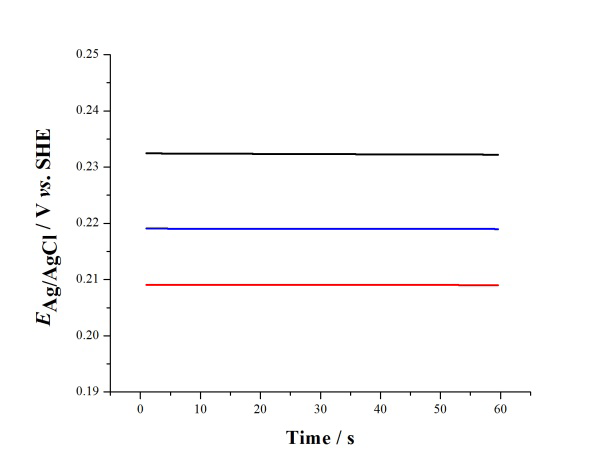
Once the RE has been prepared, the theoretical and experimental potential values can be determined and compared. Equation 4 should be used to calculate the theoretical value of the RE potential, Ag AgCl E , versus the RE chloride concentration, ln[Cl–]. Meanwhile, the potential of the new RE is measured versus the laboratory-standard RE using a voltmeter or a potentiostat. The potential of different RE in the range of 1 to 3 molar is shown in Figure 4A.
![Figure 4: ** A) Plots of REs EAg/AgCl as a function of the [Cl–] concentration, corresponding to (closed squares) the theoretical data calculated using the Nernst equation (Eq 4), (open circles) experimental data obtained immediately after the REs preparation, and (open triangles) the experimental data obtained one month after the REs preparation (error bar = ±0.005V), corresponding to data in (B). The dashed line corresponds to the linear fit for the theoretical data. B) Time courses of EAg/AgCl for three different REs: Ag/AgCl, 1 M NaCl; Ag/AgCl, 2 M NaCl; and Ag/AgCl, 3 M NaCl; from top to bottom. T=22 °C.](/fulltextimages/10254/fig_4.png)
(A) (B) Figure 4: A) Plots of REs EAg/AgCl as a function of the [Cl–] concentration, corresponding to (closed squares) the theoretical data calculated using the Nernst equation (Eq 4), (open circles) experimental data obtained immediately after the REs preparation, and (open triangles) the experimental data obtained one month after the REs preparation (error bar = ±0.005V), corresponding to data in (B). The dashed line corresponds to the linear fit for the theoretical data. B) Time courses of EAg/AgCl for three different REs: Ag/AgCl, 1 M NaCl; Ag/AgCl, 2 M NaCl; and Ag/AgCl, 3 M NaCl; from top to bottom. T=22 °C.
Procedure to Test the Reference Electrode with a Voltmeter
• Place the recently constructed (or the RE to test) and the laboratory-standard reference electrode in an electrochemical cell containing a NaCl solution with the Figure 4B shows examples of open-circuit potential measurements obtained using a potentiostat. For each chloride concentration, the RE potential values measured for different RE were reproducible to within ± 0.003V and always inside the error bars of ± 0.005 V corresponding to the theoretical potential values. The average values obtained right after assembling the REs and that obtained after one month of storage are reported in Figure 4A.
same molarity as that inside the RE to test (e.g., 3 M NaCl solution for Ag/AgCl, 3M NaCl). • Connect the laboratory-standard RE to the BLACK lead (negative terminal) of a voltmeter, and the RE just assembled (or the RE to test) to the RED lead (positive terminal, Figure 5).
• Turn on the voltmeter and measure the potential (in millivolts) until it settles. The RE must be evaluated if the potential takes a long time to settle. In addition, check and elimination of any bubbles trapped inside the RE are needed. Besides, the vycor frit should be evaluated for damage or clogging. A RE evaluated this way is acceptable if its potential is within ± 5 mV of the value predicted by the Nernst equation for the same chloride concentration. If not in this range, then the reference electrode should be re-constructed.
Note: The two electrodes should not be left connected to the voltmeter or the potentiostat, as described below, for an extended duration since, to measure the potential, a small, nonzero current must flow. This can damage the reference electrodes. Procedure to Test the Reference Electrode with a Potentiostat
- Using the same electrochemical cell, connect the laboratory-standard reference electrode to the potentiostat as the RE and the RE to test as the working electrode.
- Turn on the potentiostat and measure the open-circuit potential (OCP) versus time for 30-60 seconds. Calculate the potential of your reference electrode vs. the laboratory-standard reference electrode.
Note: do not attempt to control the current or the potential. Besides, some potentiostats may require the connection of the counter electrode terminal to the reference electrode terminal for this measurement.
Storage of the Reference Electrodes
The reference electrodes are easily ruined if the vycor tip dries out. Keep the tips wet and store the electrode in a NaCl solution (same NaCl concentration as inside the RE) when not in use. Do not entirely immerse the reference electrodes in the storage solution. Keep the connecting pin dry, or they will corrode and affect the connections to the potentiostat. Besides, the Vycor should not touch the container floor. A schematic guide on how to store it is shown in Figure 6.
Conclusion
In this work, the protocol to construct Ag/AgCl RE with different NaCl concentrations was presented, and the experimental RE potentials were measured using two different techniques and compared to those obtained using the Nernst equation. The RE potential similarities or differences observed when the RE contains different NaCl concentrations were also discussed. Furthermore, using an electrolytic cell to deposit AgCl onto the silver wire part of the RE and determining the mass of AgCl formed by using Faraday’s law of electrolysis were presented. These reference electrodes are easily constructed, and the materials needed are readily available and non-toxic. Furthermore, the reference electrodes exhibited good potential stability as a function of time.
References
-
The silver wire is immersed in 25% ammonia solution for a few minutes and then rinsed thoroughly with deionized water. After this cleaning step, the silver wire is immersed into an electrochemical cell (electrolytic cell) containing 0.1 M HCl solution and connected to the potentiostat as the working electrode. A platinum wire is used as the reference and counter electrode in this cell. A chronocoulometry (or chronoamperometry followed by data integration) is then performed by applying a potential of 0.5 V for 30 min (the data of this experiment could be used to calculate the mass of AgCl formed). Then, the coated wire is washed with doubly distilled water. The colour of the AgCl-coated silver wire should be sepia (dark brown with a reddish tint) if chloridized in the absence of light or pale tan to brown if chloridized while exposed to a light source (Figure 2). [INLINE_FIGURE:2:0] Figure 2: Silver wire before (A) and after (B) the chronocoulometric experiment. The AgCl-coated silver wire is then introduced into the RE glass holder (Figure 1) and placed into the storage recipient containing a NaCl solution, which concentration matches the internal RE solution.
- Superposition of Cryo-EM and AlphaFold Predictions of Dengue Antigen-Antibody Complexes
- Jugular-Applied Coherent Low-Level Laser Therapy Enhances Systemic Mitochondrial Metabolic Function and Antioxidant Response
- Role of OMC32 Polypeptide in Acrosin-Mediated Exocytosis during the Bovine Sperm Acrosome Reaction
- Association of Galectin-3 but not Laminin in Tamoxifen-Induced Growth Suppression in Breast Cancer MCF-7 Cells
- Effect of Different Wavelengths of Light on the Rate of Photosynthesis
- Nutritional, Therapeutic, and Environmental Effect of Oyster Mushrooms: An Editorial