Comparative Study on Seismic Performance of Steel Building & Composite Building with CFT & CFST Column
In this paper a comparative study is done on Steel building & Composite building with CFT, CFT with stiffeners, CFDST Hollow & CFDST column. Seismic Analysis of (B+G+9) building is done in both Equivalent Static method & Response Spectrum method using ETABS software & Optimum Composite column is obtained from Parameter 1 (Steel Ratio, Buckling Load, Plastic Resistance, H/T Ratio), Parameter 2 (Displacement, Story Drift, Base Shear, Overturning Moment, Story Stiffness), Parameter3 (Moment of Inertia, C/S Area, Total Weight, Total Tonnage).
Introduction
- In-present, composite structures are becoming more popular in INDIA due to the benefits in structural performance and construction sequence.
- Due to the adoption & advancement of composite structures, the buildings are becoming more slender, having longer span, has increase in stiffness and Buckling Load, has Reduction in total Tonnage and C/S Area of the composite column than R.C.C and Steel column and the performance is good in case of earthquake conditions.
- CFT (Concrete Filled Tubes) column is a type of composite column, where local buckling is delayed by concrete core & buckling load of concrete is increased by the confinement effect of steel tube.
- CFT with stiffeners is same as CFT column but this column has additional steel plates in longitudinal or transversal direction of the column, this addition of steel plate is to increase the stiffness of composite column by increasing the steel ratio of the column.
- CFDST Hollow (Concrete Filled Double Skin Tubes) is a creative innovation which is formed by two layers of steel tube which is embedded by a concrete layer between these steel tubes. The second layer of steel tube is left hollow to reduce the C/A area & weight of the column. It has additional advantages like high strength, high stiffness, good seismic and fire performance.
- CFDST column is same as the above column, but the second layer of steel tube is filled with high strength concrete or same grade of concrete as of the embedded concrete.
- This type of column is normally used when the building has very high axial load which is commonly used in High- Rised building.
- The design of composite slab & composite column is done as per Eurocode 4.
Objective
- To Study the characteristics and structural performance of building with inclusion of CFT (Concrete Filled Tubes), CFT with Stiffeners, CFDST Hollow & CFDST (Concrete Filled double Skin Tubes) columns.
- To analyse the building in Response Spectrum method.
- To obtain the effective performance of different composite column using Parameter 1 (Buckling Load, Plastic Resistance, H/T Ratio, Steel Ratio) & Parameter 2 (Displacement, Story Drift, Base Shear, Overturning moment, Stiffness) in ETABS.
- To find the Optimum Tonnage for different types of columns.
Scope
• Analytical study on the Seismic performance of Composite building with CFT (Concrete Filled Tubes), CFT with Stiffeners, CFDST Hollow & CFDST (Concrete Filled Double Skin Tubes) composite columns & comparing with Steel building by Response Spectrum method.
Methodology
- Literature survey.
- Using different types of Composite column by changing its inner tube dimension (75,100,150,200,250,300mm) & thickness of tubes (i.e., column with same inner & outer tube dimension (ST), column with thick inner & thin outer tube dimension (IT), column with thin inner & thick outer tube dimension (OT)) [1].
- Seismic Analysis of the model by both Equivalent Static Method & Response Spectrum Method is performed in ETABS [2].
- The considered parameters are, Parameter 1(Buckling Load, Plastic Resistance, H/T Ratio, Steel Ratio), Parameter 2(Displacement, Storey Drift, Base Shear, overturning moment, Stiffness), Parameter 3(C/S Area, Total Tonnage) [3].
- Obtaining the Optimum column with respect to different parameters [4].
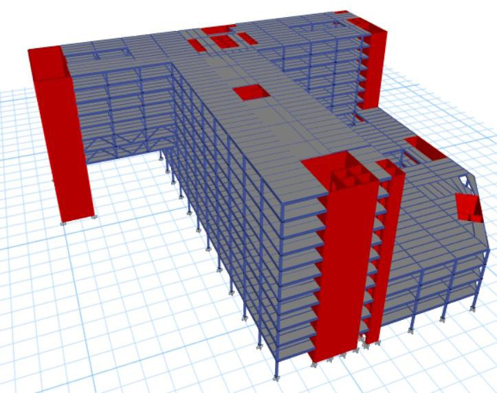
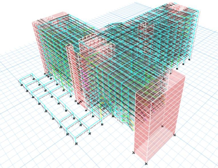
Structural System
Steel Structure: The structural system consists of Steel Beams, Deck Slabs, Steel Columns, Footing and RC core. Transfer Girders will be supporting the floors which is cantilever [5]. Composite Structure: The structural system consists of Steel Beams, Deck Slabs, CFT, CFT with Stiffeners, CFDST Hollow & CFDST Composite Columns with different steel ratio, Footing and RC Core. Transfer Girders will be supporting the floors which is cantilever (Table 1).
| Steel Grade for Steel Building | Steel Grade for Composite Building | |
|---|---|---|
| Columns | Fe350 | S355 |
| Beam | Fe350 | Fe350 |
| Deck Slab | Fe350 | Fe350 |
| Inclined Member | Fe350 | Fe350 |
Table 1: Grade of Steel.
Design Methodology
All Steel structures are designed according to the Limit State Method as specified in IS 800:2007 and the Deck Slab is designed as per ASCI 360-16. Composite column is manually designed as per Euro code 4. Appropriate loads and its combination for the building are considered as per relevant IS codes [6].
Earthquake Load
The loading due to earthquake is assumed based on the provisions of IS1893:2016 considering seismic zone – III [7].
Design factors:
- Zone factor, Z = 0.16
- Importance Factor, I = 1.5 (Hospital Building)
- Response reduction factor, R = 4.0 (Steel Building)
- Response reduction factor, R = 4.0 (Composite Building)
- Damping Ratio= 5%
Beam and Column Orientation
The beams and columns are orientated based on the shear force and bending moment diagrams. The orientation for typical floor & 3D View is as follows (Tables 2-6):
Different Types of Composite Column
CFT- Concrete Filled Tube CFT(S)- Concrete Filled Tube with Stiffeners CFDST Hollow- Concrete Filled Double Skin Tube with inner Hollow (ST1)- CFDST Hollow of same thickness (IT1)- CFDST Hollow of Inner thick Tube (OT1)- CFDST Hollow of Outer thick Tube CFDST- Concrete Filled Double Skin Tube (ST2)- CFDST of same thickness (IT2)- CFDST of Inner thick Tube (OT2)- CFDST of Outer thick Tube
Different Composite Columns used in Building
| Composite Column Section | OUTER TUBE Dimension | Inner Tube Dimension | Figure | ||||
|---|---|---|---|---|---|---|---|
| B | L | T | B | L | T | ||
| mm | mm | mm | mm | mm | mm | ||
| CFT | 450 | 450 | 12 | - | - | - | |
| CFT(S) | 450 | 450 | 12 | 4 nos. Plate Section (75x8mm) | |||
| ST1 | 450 | 450 | 12 | 75-300 | 75-300 | 12 | |
| IT1 | 450 | 450 | 8 | 75-300 | 75-300 | 16 | N/A |
| OT1 | 450 | 450 | 16 | 75-300 | 75-300 | 8 | |
| ST2 | 450 | 450 | 12 | 75-300 | 75-300 | 12 | |
| IT2 | 450 | 450 | 8 | 75-300 | 75-300 | 16 | N/A |
| OT2 | 450 | 450 | 16 | 75-300 | 75-300 | 8 | |
| TOTAL |
Table 2: Different Composite Columns used in Building.
Model Output
Parameter 1 (Steel Ratio, Buckling Load, Plastic Resistance, H/T Ratio)
| CFT | CFT (S) | (ST1) | (IT1) | (OT1) | (ST1) | (IT1) | (OT1) | (ST1) | (IT1) | (OT1) | (ST1) | (IT1) | (OT1) | (ST1) | (IT1) | (OT1) | (ST1) | (IT1) | (OT1) | THICK NESS LIMIT | |
|---|---|---|---|---|---|---|---|---|---|---|---|---|---|---|---|---|---|---|---|---|---|
| Inner steel tube | - | - | 75 | 75 | 75 | 100 | 100 | 100 | 150 | 150 | 150 | 200 | 200 | 200 | 250 | 250 | 250 | 300 | 300 | 300 | - |
| Steel Ratio | 0.35 | 0.37 | 0.38 | 0.32 | 0.42 | 0.39 | 0.34 | 0.42 | 0.41 | 0.38 | 0.44 | 0.44 | 0.42 | 0.47 | 0.48 | 0.46 | 0.5 | 0.52 | 0.5 | 0.53 | - |
| Buckling Load | 8704 | 9040 | 11646 | 9965 | 13238 | 11841 | 10251 | 13337 | 12158 | 10759 | 13455 | 12386 | 11194 | 13468 | 12521 | 11561 | 13372 | 12556 | 11852 | 13156 | - |
| Plastic Resistance | 12592 | 13290 | 13388 | 11631 | 15067 | 13635 | 12007 | 15185 | 14010 | 12640 | 15302 | 14225 | 13112 | 15258 | 14279 | 13425 | 15054 | 14174 | 13578 | 14691 | - |
| H/T Ratio (outer Tube) | 37.5 | 37.5 | 37.5 | 56.25 | 28.13 | 37.5 | 56.25 | 28.13 | 37.5 | 56.25 | 28.13 | 37.5 | 56.25 | 28.13 | 37.5 | 56.25 | 28.13 | 37.5 | 56.25 | 28.13 | 42.31 |
| H/T Ratio (InnerTube) | - | - | 6.25 | 4.69 | 9.38 | 8.33 | 6.25 | 12.5 | 12.5 | 9.38 | 18.75 | 16.67 | 12.5 | 25 | 20.83 | 15.63 | 31.25 | 25 | 18.75 | 37.5 | 42.31 |
Table 3: Comparison of Different CFDT Hollow Column.
| (OT1) | (OT1) | (OT1) | (OT1) | (OT1) | (OT1) | (RS1) | (RS1) | (RS1) | (RS1) | (RS1) | Thickness Limit | |
|---|---|---|---|---|---|---|---|---|---|---|---|---|
| Outer Steel Tube Dimension | 450 | 450 | 450 | 450 | 450 | 450 | 375 | 375 | 375 | 375 | 375 | - |
| Inner Steel Tube Dimension | 75 | 100 | 150 | 200 | 250 | 300 | 75 | 100 | 150 | 200 | 250 | - |
| Steel Ratio | 0.42 | 0.42 | 0.44 | 0.47 | 0.5 | 0.53 | 0.45 | 0.46 | 0.48 | 0.51 | 0.55 | - |
| Buckling Load | 13238 | 13337 | 13455 | 13468 | 13372 | 13156 | 9625 | 9718 | 9841 | 9877 | 9821 | - |
| Plastic Resistance | 15067 | 15185 | 15302 | 15258 | 15054 | 14691 | 11692 | 11810 | 11926 | 11883 | 11679 | - |
| H/T Ratio (Outer Tube) | 28.13 | 28.13 | 28.13 | 28.13 | 28.13 | 28.13 | 23.44 | 23.44 | 23.44 | 23.44 | 23.44 | 42.31 |
| H/T Ratio (Inner Tube) | 9.38 | 12.5 | 18.75 | 25 | 31.25 | 37.5 | 9.38 | 12.5 | 18.75 | 25 | 31.25 | 42.31 |
Table 4: Comparison of OT1 & RS1 Column.
| CFT | CFT(S) | CFDST(ST2)75 | CFDST(IT2)75 | CFDST(OT2)75 | CFDST(ST2)100 | CFDST(IT2)100 | CFDST(OT2)100 | CFDST(ST2)150 | CFDST(IT2)150 | CFDST(OT2)150 | CFDST(ST2)200 | CFDST(IT2)200 | CFDST(OT2)200 | CFDST(ST2)250 | CFDST(IT2)250 | CFDST(OT2)250 | CFDST(ST2)300 | CFDST(IT2)300 | CFDST(OT2)300 | THICKNESS LIMIT | |
|---|---|---|---|---|---|---|---|---|---|---|---|---|---|---|---|---|---|---|---|---|---|
| Inner Steel Tube Dimension | - | - | 75 | 75 | 75 | 100 | 100 | 100 | 150 | 150 | 150 | 200 | 200 | 200 | 250 | 250 | 250 | 300 | 300 | 300 | - |
| Steel Ratio | 0.35 | 0.37 | 0.48 | 0.43 | 0.51 | 0.48 | 0.44 | 0.51 | 0.5 | 0.47 | 0.52 | 0.51 | 0.49 | 0.52 | 0.52 | 0.5 | 0.5 | 0.53 | 0.52 | 0.53 | - |
| Buckling Load | 8704 | 9040 | 9500 | 7741 | 11178 | 9789 | 8120 | 11372 | 10372 | 8884 | 11765 | 10972 | 9674 | 12166 | 11595 | 10505 | 12577 | 12245 | 11388 | 12997 | - |
| Plastic Resistance | 12592 | 13290 | 10616 | 8737 | 12417 | 10984 | 9227 | 12663 | 11720 | 10209 | 13153 | 12457 | 11190 | 13644 | 13193 | 12172 | 14135 | 13929 | 13153 | 14626 | - |
| H/T Ratio (outer tube) | 37.5 | 37.5 | 37.5 | 56.25 | 28.13 | 37.5 | 56.25 | 28.13 | 37.5 | 56.25 | 28.13 | 37.5 | 56.25 | 28.13 | 37.5 | 56.25 | 28.13 | 37.5 | 56.25 | 28.13 | 42.31 |
| H/T Ratio (Inner tube) | - | - | 6.25 | 4.69 | 9.38 | 8.33 | 6.25 | 12.5 | 12.5 | 9.38 | 18.75 | 16.67 | 12.5 | 25 | 20.83 | 15.63 | 31.25 | 25 | 18.75 | 37.5 | 42.31 |
Table 5: Comparison of Different CFDT Column.
| (OT2)75 | (OT2)100 | (OT2)150 | (OT2)200 | (OT2)250 | (OT2)300 | (RS2)75 | (RS2)100 | (RS2)150 | (RS2)200 | (RS2)250 | THICKNESS LIMIT | |
|---|---|---|---|---|---|---|---|---|---|---|---|---|
| Outer Steel Tube Dimensions | 450 | 450 | 450 | 450 | 450 | 450 | 375 | 375 | 375 | 375 | 375 | - |
| Inner Steel Tube Dimensions | 75 | 100 | 150 | 200 | 250 | 300 | 75 | 100 | 150 | 200 | 250 | - |
| Steel Ratio | 0.51 | 0.51 | 0.52 | 0.52 | 0.5 | 0.53 | 0.53 | 0.53 | 0.54 | 0.55 | 0.55 | - |
| Buckling Load | 11178 | 11372 | 11765 | 12166 | 12577 | 12997 | 8451 | 8592 | 8953 | 9330 | 9726 | - |
| Plastic Resistance | 12417 | 12663 | 13153 | 13644 | 14135 | 14626 | 10011 | 10200 | 10691 | 11182 | 11673 | - |
| H/T Ratio (Outer Tube) | 28 | 28 | 28 | 28 | 28 | 28 | 23 | 23 | 23 | 23 | 23 | 42.31 |
| H/T Ratio (Inner Tube) | 9.38 | 12.5 | 18.75 | 25 | 31.25 | 37.5 | 9.38 | 12.5 | 18.75 | 25 | 31.25 | 42.31 |
Table 6: Comparison of OT2 & RS2 Column.
Output 1
- Load carrying capacity of CFT column is greater than Steel column [8].
- CFT(S) has higher Buckling Load than CFT column due to increase in Steel Ratio [9].
- CFDST Hollow column • Considering dimension for CFT, CFDST HOLLOW, composite column are 450X450 mm, 650X650mm, 800X800mm & for RS1 the column dimension is 375X375mm, 575X575mm, 725X725mm. • CFDST Hollow (IT
| CFDST Hollow column | ||||||
|---|---|---|---|---|---|---|
| RSX | STEEL | CFT | CFT(S) | (ST1) | (OT1) | (RS1) |
| DISPLACEMENT | 11.066 | 11.139 | 11.159 | 11.137 | 11.126 | 11.149 |
| STORY DRIFT | 0.000284 | 0.000286 | 0.000286 | 0.000286 | 0.000285 | 0.000286 |
| BASE SHEAR | 65286 | 65058.4 | 65007.8 | 64652 | 64687.2 | 64241.2 |
Table 7: Comparison of CFDST Hollow Column in X-Direction
Output 2
- Displacement & Story Drift of CFT column has a percentage increase of 0.66% & 0.70% respectively and the Base Shear, Overturning Moment, Stiffness of CFT column has percentage decrease of 0.35%, 0.25%, 3.59% when compared to Steel column. So, CFT column performs good when compared to Steel column [11].
- Displacement, Stiffness of CFT(S) column has a percentage increase of 0.18%, 0.13% respectively and the Base Shear, Overturning Moment of CFT(S) column has a percentage decrease of 0.08%, 0.11%, when compared to CFT column. So, CFT(S) column performs well when compared to CFT column [12].
- CFDST Hollow column: • Displacement, Base Shear, Overturning Moment of ST1 column has a percentage decrease of 0.02%, 0.62%, 0.66% respectively and the Stiffness of ST1 column has a percentage increase of 11.03% when compared to CFT column.
So, ST1 column performs good when compared to CFT column [13].
- Displacement, Story Drift, Base Shear, Overturning Moment of OT1 column has a percentage decrease of 0.12%, 0.35%, 0.57%, 0.61% respectively and the Stiffness of OT1 column has a percentage increase of 16.91% when compared to CFT column. So, OT1 column performs good when compared to CFT column [14].
- Displacement, Story Drift of OT1 column has a percentage decrease of 0.10%, 0.35% respectively and the Base Shear, Overturning Moment, Stiffness of OT1 column has a percentage increase of 0.05%, 0.06%, 6.61% when compared to ST1 column. So, OT1 column performs good when compared to ST1 column [15].
- Displacement, Story Drift, Base Shear, Overturning Moment, Stiffness of RS1 column has a percentage decrease of 0.21%, 0.35%, 0.69%, 0.71%, 36.78% respectively when compared to OT1 column. So, RS1 column performs good when compared to OT1 column [16].
- In ST1, OT1, RS1 columns considering different inner tube dimensions such as 75,100,150,200,250,300mm, larger dimension tube performs good in considered parameters [17].
4. CFDST column: • Displacement, Story Drift of ST2 column has a percentage increase of 0.70%, 0.69% respectively and the Base Shear, Overturning Moment, Stiffness of ST2 column has a percentage decrease of 0.10%, 0.12%, 1.10% when compared to CFT column. ST2 column performs good when compared to CFT column [18].
• Displacement, Story Drift, Base Shear, Overturning Moment, Stiffness of OT2 column has a percentage increase of 0.81%, 0.69%, 0.07%, 0.03%, 4.45% respectively when compared to CFT column. CFT column performs good when compared to OT2 column because the grade provided in CFT column is M60 & grade provided in OT2 column is M30 (Outer & Inner) [19].
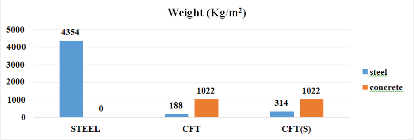
Parameter 3
(Moment of Inertia, C/S Area, Total Weight, Total Tonnage) Tables 8-10.
| Weight (Kg/m2) | Total Weight (Kg/m2) | Total Tonnage | Percentage Reduction | ||
|---|---|---|---|---|---|
| steel | concrete | ||||
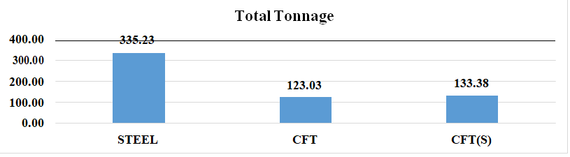
| STEEL | 4354 | - | 4354 | 335.23 | - |
| CFT | 188 | 1022 | 1211 | 123.03 | 63.3 |
| CFT(S) | 314 | 1022 | 1336 | 133.38 | 60.21 |
Table 8: Comparison of Steel & Composite Column.
| Weight (Kg/m2) | Total Weight (Kg/m2) | Total Tonnage | Percentage Increase | ||
|---|---|---|---|---|---|
| steel | concrete | ||||
| STEEL | 188 | 1022 | 1211 | 123.03 | - |
| CFT(S) | 314 | 1022 | 1336 | 133.38 | 7.76 |
Table 9: Comparison of CFT & CFT(S) column.
| Weight (Kg/m2) | Total Weight (Kg/m2) | Total Tonnage | Percentage Increase | ||
|---|---|---|---|---|---|
| steel | concrete | ||||
| CFT | 188 | 1022 | 1211 | 123.03 | - |
| (ST1) | 377 | 1022 | 1399 | 138.3 | 11.03 |
| (OT1) | 377 | 1003 | 1380 | 136.74 | 10.02 |
Table 10: Comparison of CFT & CFDST Hollow column.
Output 3
1. Comparing Steel, CFT & CFT(S) column, the C/S Area of CFT & CFT(S) is higher than that of Steel column. M.O.I of Steel column is high than that of CFT & CFT(S) and the Total Tonnage of CFT & CFT(S) column is less than that of Steel column where the Percentage of Reduction in Tonnage is 63.30% and 60.21% respectively [20].
2. Comparing CFT, CFT(S) composite column, C/S Area & M.O.I of both columns are same. The Total Tonnage of CFT(S) is higher than that of CFT, where the percentage increase is 7.76% with respect to CFT column [21].
3. CFDST Hollow column
- Comparing CFT, ST1, OT1 composite column, OT1 has less C/S Area than other columns (OT1<ST1<CFT). There is no significant change in M.O.I. The Total Tonnage of CFT is less than that of ST1, OT1 where the Percentage Increase is 11.03% & 10.02% for ST1 & OT1 respectively. (CFT<OT1<ST1) [22].
- Eliminating ST1 due to high Total Tonnage & less Buckling Load comparative to OT1 [23].
- So, while comparing the CFT & OT1 in Parameter 1, OT1 performs well and in Parameter 2 OT1 performs well and in Parameter 3 CFT performs well (where the Tonnage of CFT is less than that of OT1). So, the Reduced Size of OT1 comes in account and it is coined as Reduced Size RS1 [24].
- Comparing CFT, OT1, RS1 composite column, C/S Area of RS1 has less C/S Area (RS1<OT1<CFT). M.O.I of RS1 column is less than that of CFT & OT1. The Total Tonnage of RS1 is less than that of CFT, OT1 where the Percentage Decrease in Tonnage for RS1 is 0.71% when compared to CFT & Percentage Decrease for RS1 is 10.66% when compared to OT1 (RS1<CFT<OT1) [25].
Results
- Comparing Steel & CFT Column, in Parameter 1,2,3, CFT column performs better than Steel column. Steel column can be replaced by CFT column.
- Comparing CFT & CFT(S) Column, in Parameter 1,2, CFT(S) column performs better than CFT column and in Parameter 3 CFT column performs better than CFT(S) column.
- CFT column can be replaced by CFT(S) column only in parameter 1&2, but CFT is optimum in parameter
Conclusion
The Steel & Composite Building is compared with 3 different parameters, in which CFT column performs better than Steel Column. CFT(S) column performs good than CFT column. OT1 column performs better than CFT, ST1, ST2 & OT2 column. RS1 column performs better than CFT, OT1, OT2 and RS2 column. To conclude CFT column is a better replacement for Steel column. CFT(S) column is a better replacement (without increasing the column dimension) for CFT column when building has slightly higher buckling load. OT1 column is best replacement (without increasing the column dimension) for CFT column due to the Hollow inner tube which provides less C/S Area without compromising the buckling load. CFDST column is not optimum as CFDST Hollow column, where the inner tubes are filled with higher grade of concrete.
References
-
IS 875 (part1): 1987 Code of practice for design loads (other than earthquake) for buildings and structures – unit weight of buildings materials and stored materials. pp: 1-37.
-
IS 875 (part2): 1987 Code of practice for design loads (other than earthquake) for buildings and structures – Imposed loads. pp: 4-18.
-
IS 875 (part3): 2015 Code of practice for design loads (other than earthquake) for buildings and structures – Wind loads. pp: 1-58.
-
IS 875 (part5): 2015 Code of practice for design loads (other than earthquake) for buildings and structures – special loads and load combination. pp: 2-18.
-
IS 800 (2007) Code of practice for General Construction in Steel. pp: 1-143.
-
IS 1893 (part 1): 2016 Criteria for Earthquake Resistant Design of Structures. pp: 1-44.
-
Eurocode 4 Design of composite steel and concrete structures. pp: 2-118.
-
Laddha VR, Siddh SP, Hiwas PD (2021) Analytical Investigation of Composite Structure in Comparison of RCC Structure. International Conference on Advances in Civil Engineering pp: 1-9.
-
Gore VV, Kumbhar PD (2016) Comparative Behavioural Study of Multi Storied Building Provided with RCC and Concrete Filled Steel Tube Columns.
-
Purushothaman V, Sukumaran A (2017) Comparative Study on Seismic Analysis of Multi Storied Buildings with Composite Columns. International Journal Of Engineering Research & Technology 6(6).
-
Priya K, Narayan K, Ekta (2019) Seismic Analysis of Building with CFST and Concrete-Filled Double Skin Tubular Columns. Journal of Emerging Technologies and Innovative Research 6(6).
-
Zhang D, Zhao J, Zhang Y (2018) Experimental and Numerical Investigation of Concrete-Filled Double-Skin Steel Tubular Column for Steel Beam JOINT NUMBERs.
-
Panchal D, Marathe P (2011) Comparative Study of R.C.C, Steel and Composite (G+30 Storey) Building.
-
Uddin MA (2020) Comparative Study on Seismic Behaviour of Composite and RCC plan Irregular Structures. International Journal of Engineering Research & Technology (IJERT) 9(1).
-
Mahajan AS, Kalurkar LG (2016) “Behavior of RCC and Composite Structure under Seismic Loads”. IOSR Journal of Mechanical and Civil Engineering Vol 13(4): 96-102.
-
Mustafa M Wagh (2016) Behaviour of Concrete Filled Steel Tube with Reference to Different Shape of Column. 3(1).
-
Tiwari NK, Singh P, Gautam R (2020) Comparative Seismic Analysis of RCC, Steel & Steel- Concrete Composite Frame Structure. International Journal of Trend in Research and Development 7(3): 222-230.
-
Zhang D, Zhao J, He S (2018) Cyclic Testing of Concrete- Filled Double-Skin Steel Tubular Column to Steel Beam Joint with RC Slab.
-
Kalingarani K, Shanmugavalli B, Sundarraja MC (2014) Axial Compressive Behaviour of Slender CFST members–Analytical Investigation. International Journal of Innovative Research in Science, Engineering and Technology 3(1): 22-25.
-
Sabith KM, Sabeena MV (2017) Seismic Analysis of Irregular Composite Structures with Shear Connectors using ETABS. International Journal of Scientific Research in Science, Engineering and Technology 3(3): 1-7.
-
Romero ML, Espinos A, Portolés JM (2015) Slender double-tube ultra-high strength concrete-filled tubular columns under ambient temperature and fire. Journal of Elsevier 19: 536-545.
-
Zhanga Q, Schafera M (2018) Comparison of design for composite columns in steel and concrete according to Eurocode 4 and Chinese design codes. Polytechnic University of Valencia.
-
Jadhav A, Sayyed AQ, Kadne V (2020) Construction of a high-rise commercial building using CFT technology in Mumbai, India. International Journal of Scientific & Engineering Research 11(5): 1136-1140.
-
Tailora A, Dalalb SP, Desaic AK(2017) Comparative Performance Evaluation of Steel Column Building & Concrete Filled Tube Column Building under Static and Dynamic Loading. Procedia Engineering Vol 173: 1847- 1853.
-
Pansuriya D, Panchal VR, Panchal DR (2018) Experimental Study on Comparison of Square, Rectangular and Circular Concrete Filled Steel Tube Composite Columns. Journal of Emerging Technologies and Innovative Research 5(7): 988-993.
- Solution-Processed Chiral Perovskites for Biomedical Applications
- Nanotechnology in Health Chemistry and Medicine: Current Challenges and Future Directions
- Human Exposure to Micro- and Nanoplastics: Pathways, Toxicity, and Intervention Strategies
- Exosome Nanomedicine for Cancer Therapy
- Micro and Nanoplastics–Plastisphere, Biotoxicity, Impact on Human Health, and Mitigation Strategies
- Process Validation of Cefixime Powder for Suspension Dosage Form, 50 mL