Structural Scheme of an Engine for Nanomedicine and Nanotechnology
The structural model of an engine is determined for nanomedicine and nanotechnology. The structural scheme of an engine for nanodisplacement is obtained. The matrix equation is constructed for an engine for nanomedicine and nanotechnology.
Introduction
A nanoengine is used for scanning microscopy for nanomedicine, nanotechnology and adaptive optics. The piezo engine is applied to penetrate the cell and manipulate genes [1, 2, 3, 4, 5, 6, 7, 8, 9, 10, 11, 12, 13, 14, 15, 16, 17, 18, 19, 20, 21, 22, 23, 24, 25]. The application of an electro magneto elastic engine in the form the piezoelectric, electrostriction or magnetostriction engine is promising for aligning the mirrors of laser optics and scanning in the atomic-force microscope [19, 20, 21, 22, 23, 24, 25, 26, 27, 28, 29, 30, 31, 32, 33, 34, 35, 36, 37, 38, 39, 40, 41, 42, 43, 44, 45, 46, 47, 48, 49, 50, 51, 52, 53, 54, 55, 56, 57, 58].
Structural Model of an Engine
The electro magneto elasticity expression [1, 2, 3, 4, 5, 6, 7, 8] is used
$$S_i = s_{ij}^{E,H} T_j + d_{mi}^{H} E_m + d_{mi}^{E} H_m$$
where $S_i$ is the relative deformation on axis $i$, $E_m$ is the electric field strength on axis $m$, $H_m$ is the magnetic field strength on axis $m$, $s_{ij}^{E,H}$ is the elastic compliance for $E = \text{const}$, $H = \text{const}$, $T_j$ is the mechanical stress on the axis $j$, $d_{mi}^{H}$ is the piezo module, $d_{mi}^{E}$ is the magnetostriction coefficient.
The expression of the reverse piezo effect [1, 2, 3, 4, 5, 6, 7, 8] has the form
$$S_i = d_{mi} E_m + s_{ij}^{E} T_j$$
where $S_i$, $d_{mi}$, $E_m$, $s_{ij}^{E}$, $T_j$ are the relative displacement, piezo module, strength electric field, elastic compliance, strength mechanical field.
The expression of the longitudinal inverse piezo effect [1, 2, 3, 4, 5, 6, 7, 8] has the form
$$S_3 = d_{33} E_3 + s_{33}^{E} T_3$$
The differential equation of an engine is used [4, 5, 6, 7, 8, 9, 10, 11, 12, 13, 14, 15, 16, 17, 18, 19, 20, 21, 22, 23, 24, 25, 26, 27, 28, 29, 30, 31, 32, 33, 34, 35, 36, 37, 38, 39, 40, 41, 42, 43, 44, 45, 46, 47, 48, 49, 50, 51, 52, 53, 54, 55, 56]
$$\frac{d^2 \Xi(x,s)}{dx^2} - \gamma^2 \Xi(x,s) = 0$$
where $\Xi(x,s)$, $s$, $x$, $\gamma$ are the transformation Laplace for displacement, the parameter, the coordinate, the coefficient of propagation. For the longitudinal piezo engine we have at $x = 0$ the deformation $\Xi(0,s) = \Xi_1(s)$ and at $x = \delta \Xi(\delta,s) = \Xi_2(s)$. The decision is calculated.
Nanomedicine & Nanotechnology Open Access
$$\Xi(x, s) = \left\{ \Xi_1(s) \text{ sh} \left[ (\delta - x) \gamma \right] + \Xi_2(s) \text{ sh} \left(x \gamma \right) \right\} / \text{sh} \left(\delta \gamma \right)$$
The set of equations for boundary conditions is determined [4, 5, 12, 13, 14, 15, 16, 17, 18, 19, 20, 21, 22, 23, 24, 25, 26, 27, 28, 29, 30, 31, 32]
$$T_3(0, s) = \frac{1}{s_{33}^E} \frac{d\Xi(x, s)}{dx} - \frac{d_{33}}{s_{33}^E} E_3(s)$$
$$T_3(\delta, s) = \frac{1}{s_{33}^E} \frac{d\Xi(x, s)}{dx} - \frac{d_{33}}{s_{33}^E} E_3(s)$$
Its structural model is written in the form
$$\Xi_1(s) = \left( M_1 s^2 \right)^{-1} \left\{ -F_1(s) + \left( \chi_{33}^E \right)^{-1} \left[ d_{33} E_3(s) - \left[ \gamma / \text{sh} \left(\delta \gamma \right) \right] \right] \times \left[ \text{ch} \left(\delta \gamma \right) \Xi_1(s) - \Xi_2(s) \right] \right\}$$
$$\Xi_2(s) = \left( M_2 s^2 \right)^{-1} \left\{ -F_2(s) + \left( \chi_{33}^E \right)^{-1} \left[ d_{33} E_3(s) - \left[ \gamma / \text{sh} \left(\delta \gamma \right) \right] \right] \times \left[ \text{ch} \left(\delta \gamma \right) \Xi_2(s) - \Xi_1(s) \right] \right\}$$
$$\chi_{33}^E = s_{33}^E / S_0$$
where $\Xi_1(s), \Xi_2(s)$ are the transforms of the displacements, $S_0$ is the area.
The expression of the longitudinal magnetostriction [1, 2, 3, 4, 5, 6, 7, 8] has the form
$$S_3 = d_{33} H_3 + s_{33}^H T_3$$
The structural model of the longitudinal magnetostriction engine is transformed in the form
$$\Xi_1(s) = \left( M_1 s^2 \right)^{-1} \left\{ -F_1(s) + \left( \chi_{33}^H \right)^{-1} \left[ d_{33} H_3(s) - \left[ \gamma / \text{sh} \left(\delta \gamma \right) \right] \right] \times \left[ \text{ch} \left(\delta \gamma \right) \Xi_1(s) - \Xi_2(s) \right] \right\}$$
$$\Xi_2(s) = \left( M_2 s^2 \right)^{-1} \left\{ -F_2(s) + \left( \chi_{33}^H \right)^{-1} \left[ d_{33} H_3(s) - \left[ \gamma / \text{sh} \left(\delta \gamma \right) \right] \right] \times \left[ \text{ch} \left(\delta \gamma \right) \Xi_2(s) - \Xi_1(s) \right] \right\}$$
$$\chi_{33}^H = s_{33}^H / S_0$$
The expression of the transverse inverse piezo effect [1, 2, 3, 4, 5, 6, 7, 8] has the form
$$S_1 = d_{31} E_3 + s_{11}^E T_1$$
The decision of the differential equation is written
$$\Xi(x, s) = \left\{ \Xi_1(s) \text{ sh} \left[ (h - x) \gamma \right] + \Xi_2(s) \text{ sh} \left(x \gamma \right) \right\} / \text{sh} \left(h \gamma \right)$$
The set of equations is obtained
$$T_1(0, s) = \frac{1}{s_{11}^E} \frac{d\Xi(x, s)}{dx} - \frac{d_{31}}{s_{11}^E} E_3(s)$$
$$T_1(h, s) = \frac{1}{s_{11}^E} \frac{d\Xi(x, s)}{dx} - \frac{d_{31}}{s_{11}^E} E_3(s)$$
The structural model of the transverse piezo engine is written
$$\Xi_1(s) = \left( M_1 s^2 \right)^{-1} \left\{ -F_1(s) + \left( \chi_{11}^E \right)^{-1} \left[ d_{31} E_3(s) - \left[ \gamma / \text{sh} \left(h \gamma \right) \right] \right] \times \left[ \text{ch} \left(h \gamma \right) \Xi_1(s) - \Xi_2(s) \right] \right\}$$
$$\Xi_2(s) = \left( M_2 s^2 \right)^{-1} \left\{ -F_2(s) + \left( \chi_{11}^E \right)^{-1} \left[ d_{31} E_3(s) - \left[ \gamma / \text{sh} \left(h \gamma \right) \right] \right] \times \left[ \text{ch} \left(h \gamma \right) \Xi_2(s) - \Xi_1(s) \right] \right\}$$
$$\chi_{11}^E = s_{11}^E / S_0$$
The expression of the transverse magnetostriction [1, 2, 3, 4, 5, 6, 7, 8] has the form
$$S_1 = d_{31} H_3 + s_{11}^H T_1$$
The structural model is determined in the form
$$\Xi_1(s) = \left( M_1 s^2 \right)^{-1} \left\{ -F_1(s) + \left( \chi_{11}^H \right)^{-1} \left[ d_{31} H_3(s) - \left[ \gamma / \text{sh} \left(h \gamma \right) \right] \right] \times \left[ \text{ch} \left(h \gamma \right) \Xi_1(s) - \Xi_2(s) \right] \right\}$$
Nanomedicine & Nanotechnology Open Access
$$\Xi_2(s) = \left( M_2 s^2 \right)^{-1} \begin{cases} -F_2(s) + \left( \chi_{11}^H \right)^{-1} \\ \times \left[ d_{31} H_3(s) - \left[ \gamma/\text{sh}(h\gamma) \right] \\ \times \left[ \text{ch}(h\gamma) \Xi_2(s) - \Xi_1(s) \right] \end{cases}$$
$$\chi_{11}^H = s_{11}^H / S_0$$
The expression of the shift inverse piezo effect [1, 2, 3, 4, 5, 6, 7, 8] has the form
$$S_5 = d_{15} E_1 + s_{55}^E T_5$$
The decision of the differential equation is calculated
$$\Xi(x,s) = \left\{ \Xi_1(s) \text{sh} \left[ (b-x)\gamma \right] + \Xi_2(s) \text{sh}(x\gamma) \right\} / \text{sh}(b\gamma)$$
The set of equations for the shift piezo engine is written
$$T_3(0,s) = \frac{1}{s_{55}^E} \frac{d\Xi(x,s)}{dx} \Bigg|_{x=0} - \frac{d_{15} E_1(s)}{s_{55}^E} E_1(s)$$
$$T_5(b,s) = \frac{1}{s_{55}^E} \frac{d\Xi(x,s)}{dx} \Bigg|_{x=b} - \frac{d_{15} E_1(s)}{s_{55}^E} E_1(s)$$
Its structural model has the form
$$\Xi_1(s) = \left( M_1 s^2 \right)^{-1} \begin{cases} -F_1(s) + \left( \chi_{55}^E \right)^{-1} \\ \times \left[ d_{15} E_1(s) - \left[ \gamma/\text{sh}(b\gamma) \right] \\ \times \left[ \text{ch}(b\gamma) \Xi_1(s) - \Xi_2(s) \right] \end{cases}$$
$$\Xi_2(s) = \left( M_2 s^2 \right)^{-1} \begin{cases} -F_2(s) + \left( \chi_{55}^E \right)^{-1} \\ \times \left[ d_{15} E_1(s) - \left[ \gamma/\text{sh}(b\gamma) \right] \\ \times \left[ \text{ch}(b\gamma) \Xi_2(s) - \Xi_1(s) \right] \end{cases}$$
$$\chi_{55}^E = s_{55}^E / S_0$$
The expression of the shift magnetostriction [1, 2, 3, 4, 5, 6, 7, 8] has the form
$$S_5 = d_{15} H_1 + s_{55}^H T_5$$
The structural model of the shift magnetostrictive engine is transformed
$$v_{mi} = \begin{cases} d_{33}, d_{31}, d_{15} \\ g_{33}, g_{31}, g_{15} \\ d_{33}, d_{31}, d_{15} \end{cases}$$
At $l = \{\delta, h, b\}$ the decision of the differential equation of an engine in general has the form
$$\Xi(x,s) = \left\{ \Xi_1(s) \text{sh} \left[ (l-x)\gamma \right] + \Xi_2(s) \text{sh}(x\gamma) \right\} / \text{sh}(l\gamma)$$
The set of equations is determined
$$T_j(0,s) = \frac{1}{s_{ij}^E} \frac{d\Xi(x,s)}{dx} \Bigg|_{x=0} - \frac{v_{mi}}{s_{ij}^E} \Psi_m(s)$$
$$T_j(l,s) = \frac{1}{s_{ij}^E} \frac{d\Xi(x,s)}{dx} \Bigg|_{x=l} - \frac{v_{mi}}{s_{ij}^E} \Psi_m(s)$$
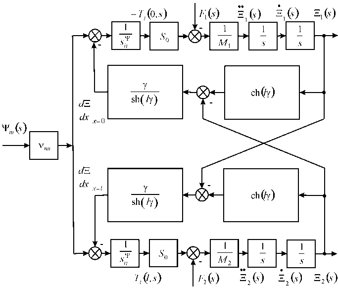
The structural model in general of an engine on Figure 1 is calculated
$$\Xi_1(s) = \left( M_1 s^2 \right)^{-1} \begin{cases} -F_1(s) + \left( \chi_{ij}^E \right)^{-1} \\ \times \left[ v_{mi} \Psi_m(s) - \left[ \gamma/\text{sh}(l\gamma) \right] \\ \times \left[ \text{ch}(l\gamma) \Xi_1(s) - \Xi_2(s) \right] \end{cases}$$
$$\Xi_2(s) = \left( M_2 s^2 \right)^{-1} \begin{cases} -F_2(s) + \left( \chi_{ij}^E \right)^{-1} \\ \times \left[ v_{mi} \Psi_m(s) - \left[ \gamma/\text{sh}(l\gamma) \right] \\ \times \left[ \text{ch}(l\gamma) \Xi_2(s) - \Xi_1(s) \right] \end{cases}$$
$$\chi_{ij}^E = s_{ij}^E / S_0$$
here
$$v_{mi} = \begin{cases} d_{33}, d_{31}, d_{15} \\ g_{33}, g_{31}, g_{15} \\ d_{33}, d_{31}, d_{15} \end{cases}$$
, , , E E D D H H
$$ \Psi_ {m} = \left\{ \begin{array}{l} I \\ I \\ I \end{array} \right. $$
3 1
3 1 m
3 1 $$ \begin{array}{l} s _ {i j} ^ {\Psi} = \left\{ \begin{array}{l l} s _ {3 3} ^ {E}, s _ {1 1} ^ {E}, s _ {5 5} ^ {E} \\ s _ {3 3} ^ {D}, s _ {1 1} ^ {D}, s _ {5 5} ^ {D} \\ s _ {3 3} ^ {H}, s _ {1 1} ^ {H}, s _ {5 5} ^ {H} \end{array} \right. \\ \gamma = \left\{\gamma^ {E}, \gamma^ {D}, \gamma^ {H} \right. \\ \end{array} $$ E E E , , , , , , s s s s s s s s s s
33 11 55 D D D ij H H H
33 11 55
33 11 55 $$ c ^ {\Psi} = \left\{c ^ {E}, c ^ {D}, c ^ {H} \right. $$
The matrix of deformations is calculated ( ) ( ) ( )
m s s W s W s W s F s s W s W s W s F s
$$ \left( \begin{array}{l} \Xi_ {1} (s) \\ \Xi_ {2} (s) \end{array} \right) = \left( \begin{array}{l l l} W _ {1 1} (s) & W _ {1 2} (s) & W _ {1 3} (s) \\ W _ {2 1} (s) & W _ {2 2} (s) & W _ {2 3} (s) \end{array} \right) \left( \begin{array}{l} \Psi_ {m} (s) \\ F _ {1} (s) \\ F _ {2} (s) \end{array} \right) $$ ( ) ( ) ( ) ( ) ( ) ( ) ( ) ( )
1 11 12 13 1 2 21 22 23 2
$$ W _ {1 1} (s) = \Xi_ {1} (s) / \Psi_ {m} (s) = \nu_ {m i} \left[ M _ {2} \chi_ {i j} ^ {\Psi} s ^ {2} + \gamma \operatorname {t h} \left(l \gamma / 2\right) \right] / A _ {i j} $$ $$ \begin{array}{l} A _ {i j} = M _ {1} M _ {2} \left(\chi_ {i j} ^ {\Psi}\right) ^ {2} s ^ {4} + \left\{\left(M _ {1} + M _ {2}\right) \chi_ {i j} ^ {\Psi} / \left[ c ^ {\Psi} \operatorname {t h} \left(l \gamma\right) \right] \right\} s ^ {3} + \left[ \left(M _ {1} + M _ {2}\right) \chi_ {i j} ^ {\Psi} \alpha / \operatorname {t h} \left(l \gamma\right) + 1 / \left(c ^ {\Psi}\right) ^ {2} \right] s ^ {2} + 2 \alpha s / c ^ {\Psi} + \alpha^ {2} \\ W _ {2 1} (s) = \Xi_ {2} (s) / \Psi_ {m} (s) = \nu_ {m i} \left[ M _ {1} \chi_ {i j} ^ {\Psi} s ^ {2} + \gamma \operatorname {t h} \left(l \gamma / 2\right) \right] / A _ {i j} \\ \end{array} $$ $$ W _ {1 2} (s) = \Xi_ {1} (s) / F _ {1} (s) = - \chi_ {i j} ^ {\Psi} \left[ M _ {2} \chi_ {i j} ^ {\Psi} s ^ {2} + \gamma / \operatorname {t h} (l \gamma) \right] / A _ {i j} $$ ( ) ( ) ( ) ( ) ( ) ( ) ( ) 13 1 2 22 2 1 sh ij ij W s s F s W s s F s l A χ γ γ Ψ = Ξ = = Ξ = ( ) ( ) ( ) ( ) 2 23 2 2 1 th ij ij ij W s s F s M s l A χ χ γ γ Ψ Ψ = Ξ = − + The static longitudinal deformations are obtained $$ \xi_ {1} = d _ {3 3} U M _ {2} / \left(M _ {1} + M _ {2}\right) $$ $$ \xi_ {2} = d _ {3 3} U M _ {1} / \left(M _ {1} + M _ {2}\right) $$ For 33 d = 4·10-10 m/V, U= 25 V, M1= 1 kg, M2= 4 kg we have $$ \xi_ {1} = 8 \mathrm {n m}, \xi_ {2} = 2 \mathrm {n m} \mathrm {a n d} \xi_ {1} + \xi_ {2} $$
= 10 nm at error 10%.
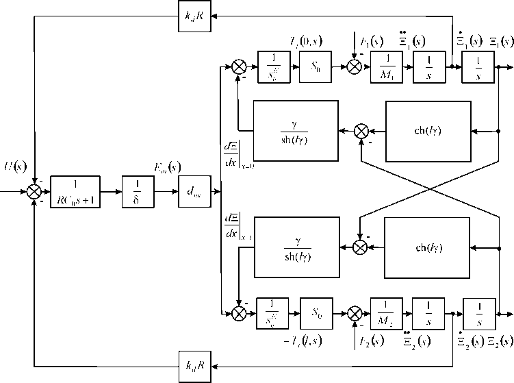
The expression of the direct piezo effect [8, 9, 10, 11, 12, 13, 14, 15, 16] is used $$ D _ {m} = d _ {m i} T _ {i} + \varepsilon_ {m k} ^ {E} E _ {k} $$ Where m D , E mk ε are the electric induction and the permittivity, The direct coefficient at voltage control is written $$ k _ {d} = \frac {d _ {m i} S _ {0}}{\delta s _ {i j} ^ {E}} $$
0 mi d E ij The expression of the transform voltage negative feedback at voltage control on Figure 2 is used d S R U s s k R s s δ $$ ) = \frac {d _ {m i} S _ {0} R}{\delta s _ {n} ^ {E}} \dot {\Xi} _ {n} (s) = k _ {d} R \dot {\Xi} _ {n} (s), n = 1, 2 $$ ( ) ( ) ( ) 0 mi d d n n E ij The maximum force at voltage control is determined $$ F _ {\max } = E _ {m} d _ {m i} S _ {0} / s _ {i j} ^ {E} $$ $$ T _ {j \max } = E _ {m} d _ {m i} / s _ {i j} ^ {E} $$
The maximum force at current control has the form $$ F _ {\max } = \frac {U}{\delta} d _ {m i} \frac {S _ {0}}{s _ {i j} ^ {E}} + \frac {F _ {\max }}{S _ {0}} d _ {m i} S _ {c} \frac {1}{\varepsilon_ {m k} ^ {T} S _ {c} / \delta} \frac {1}{\delta} d _ {m i} \frac {S _ {0}}{s _ {i j} ^ {E}} $$
1 1
0 max 0 max 0 mi mi c mi E T E ij mk c ij
$$ + \left(1 - \frac {d _ {m i} ^ {2}}{\varepsilon_ {m k} ^ {T} s _ {i j} ^ {E}}\right) s _ {i j} ^ {E} = 1 $$
2 max F d s E d S s ε
0 1 E mi ij m mi T E mk ij
$$ \left| T _ {j \max } \left(1 - k _ {m i} ^ {2}\right) s _ {i j} ^ {E} = E _ {m} d _ {m i} \right| $$
| s EεT ij mk |
|---|
here mi k is the coefficient of electromechanical coupling.
The expressions at current control are used $$ F _ {\max } = E _ {m} d _ {m i} S _ {0} / s _ {i j} ^ {D} $$ $$ T _ {j \max } = E _ {m} d _ {m i} / s _ {i j} ^ {D} $$ $$ s _ {i j} ^ {D} = \left(1 - k _ {m i} ^ {2}\right) s _ {i j} ^ {E} $$ The mechanical characteristic [11, 12, 13, 14, 15, 16, 17, 18, 19, 20, 21, 22, 23, 24, 25, 26] is determined $$ \left. S _ {i} \left(T _ {j}\right) \right| _ {\Psi = c o n s t} = \nu_ {m i} \Psi_ {m} \bigg | _ {\Psi = c o n s t} + s _ {i j} ^ {\Psi} T _ {j} $$ The adjustment characteristic [11, 12, 13, 14, 15, 16, 17, 18, 19, 20, 21, 22, 23, 24, 25, 26] is obtained ( ) i m mi m ij j T const T const S s T ν Ψ $$ \left(\Psi_ {m}\right) \bigg | _ {T = c o n s t} = \nu_ {m i} \Psi_ {m} + s _ {i j} ^ {\Psi} T _ {j} \bigg | _ {T = c c} $$ Therefore, the mechanical characteristics of the engine has the form $$ \Delta l = \Delta l _ {\max } \left(1 - F / F _ {\max }\right) $$ $$ \Delta l _ {\max } = \nu_ {m i} \Psi_ {m} l $$ $$ F _ {\max } = T _ {j \max } S _ {0} = \nu_ {m i} \Psi_ {m} S _ {0} / s _ {i j} ^ {\Psi} $$ The expression for the transverse piezo engine is calculated $$ \Delta h = \Delta h _ {\max } \left(1 - F / F _ {\max }\right) $$ $$ \Delta h _ {\max } = d _ {3 1} E _ {3} h $$ $$ F _ {\max } = d _ {3 1} E _ {3} S _ {0} / s _ {1 1} ^ {E} $$ At 31 d
= 2∙10-10 m/V,
$$ \Delta h _ {\max } = 1 2 5 \mathrm {n m}, F _ {\max } $$
= 5 N with error 10% The deformation of an engine at elastic load has the form Ψ ∆= Ψ − , e F C l = ∆ ij mi m s l F l S ν
0 The adjustment characteristic is determined l l C C ν $$ \Delta l = \frac {\nu_ {m i} l \Psi_ {m}}{1 + C _ {e} / C _ {i j} ^ {\Psi}} $$ mi m
1 e ij The coefficients in general are calculated $$ k _ {d} = k _ {r} = \frac {d _ {m i} S _ {0}}{\delta s _ {i j}} $$
0 mi d r ij $$ s _ {i j} = k _ {s} s _ {i j} ^ {E} $$
$$ \left| \left(1 - k _ {m i} ^ {2}\right) \leq k _ {s} \leq 1 \right| $$
At one fixed face and elastic-inertial load Figure 2 is transformed to Figure 3.
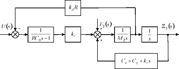
Therefore, the function of piezo engine for 0 = R has the form ( ) ( ) ( )
s k W s U s T s T s ξ $$ ) = \frac {\Xi (s)}{U (s)} = \frac {k _ {3 1} ^ {U}}{T _ {t} ^ {2} s ^ {2} + 2 T _ {t} \xi_ {t} s + 1} $$ U
31 2 2 2 1 t t t
$$ k _ {3 1} ^ {U} = d _ {3 1} \left(h / \delta\right) / \left(1 + C _ {l} / C _ {1 1} ^ {E}\right) $$ $$ T _ {t} = \sqrt {M / \left(C _ {l} + C _ {1 1} ^ {E}\right)}, \omega_ {t} = 1 / T _ {t} $$ At M= 1 kg, l C = 0.1·107, 11 E C = 1.5·107, 31 d = 2·10-10 m/V, h δ = 20 the parameters of piezo engine are calculated tT = 0.25·10-3 s, t ω = 4·103 s-1, 31 U k = 3.75 nm/V with error 10%.
Conclusions
The structural scheme of an engine is calculated for nanomedicine and nanotechnology. The matrix of the deformations of an engine is determined. The parameters of the piezo engine for nanodisplacement are obtained.
References
-
Schultz J, Ueda J, Asada H (2017) Cellular Actuators. Butterworth-Heinemann Publisher, Oxford, pp: 382.
-
Afonin SM (2006) Absolute stability conditions for a system controlling the deformation of an elecromagnetoelastic transduser. Doklady Mathematics 74(3): 943-948.
-
Uchino K (1997) Piezoelectric actuator and ultrasonic motors. Boston, MA: Kluwer Academic Publisher, pp: 350.
-
Afonin SM (2005) Generalized parametric structural model of a compound elecromagnetoelastic transduser. Doklady Physics 50(2): 77-82.
-
Afonin SM (2008) Structural parametric model of a piezoelectric nanodisplacement transducer. Doklady Physics 53(3): 137-143.
-
Afonin SM (2006) Solution of the wave equation for the control of an elecromagnetoelastic transduser. Doklady Mathematics 73(2): 307-313.
-
Cady WG (1946) Piezoelectricity: An introduction to the theory and applications of electromechancial phenomena in crystals. McGraw-Hill Book Company, New York, London, UK, pp: 806.
-
Mason W (1964) Physical Acoustics: Principles and Methods. In: Part A, Methods and Devices, Academic Press, New York, USA, pp: 515.
-
Yang Y, Tang L (2009) Equivalent circuit modeling of piezoelectric energy harvesters. Journal of Intelligent Material Systems and Structures 20(18): 2223-2235.
-
Shevtsov SN, Soloviev AN, Parinov IA, Cherpakov AV, Chebanenko VA (2018) Piezoelectric Actuators and Generators for Energy Harvesting Research and Development. Springer Cham, pp: 182.
-
Zwillinger D (1989) Handbook of Differential Equations. Academic Press, Boston, pp: 673.
-
Afonin SM (2006) A generalized structural-parametric model of an elecromagnetoelastic converter for nano- and micrometric movement control systems: III. Transformation parametric structural circuits of an elecromagnetoelastic converter for nano- and micrometric movement control systems. Journal of Computer and Systems Sciences International 45(2): 317-325.
-
Afonin SM (2006) Generalized structural-parametric model of an electromagnetoelastic converter for control systems of nano-and micrometric movements: IV. Investigation and calculation of characteristics of step- piezodrive of nano-and micrometric movements. Journal of Computer and Systems Sciences International 45(6): 1006-1013.
-
Afonin SM (2016) Decision wave equation and block diagram of electromagnetoelastic actuator nano- and microdisplacement for communications systems. International Journal of Information and Communication Sciences 1(2): 22-29.
-
Afonin SM (2015) Structural-parametric model and transfer functions of electroelastic actuator for nano- and microdisplacement. In: Parinov IA (Ed.), Piezoelectrics and Nanomaterials: Fundamentals, Developments and Applications, Nova Science, New York, USA, pp: 225-242.
-
Afonin SM (2017) A structural-parametric model of electroelastic actuator for nano- and microdisplacement of mechatronic system. In: Bartul Z, Trenor J, (Ed.), Advances in Nanotechnology, Nova Science, New York, USA, pp: 259-284.
-
Afonin SM (2018) Electromagnetoelastic nano- and microactuators for mechatronic systems. Russian Engineering Research 38(12): 938-944.
-
Afonin SM (2018) Structural-parametric model of electro elastic actuator for nanotechnology and biotechnology. Journal of Pharmacy and Pharmaceutics 5(1): 8-12.
-
Afonin SM (2012) Nano- and micro-scale piezomotors. Russian Engineering Research 32(7-8): 519-522.
-
Liu Y, Zeng A, Zhang S, Ma R, Du Z (2022) An experimental investigation on polarization process of a PZT-52 tube actuator with interdigitated electrodes. Micromachines 13(10): 1760.
-
Liu Y, Zhang S, Yan P, Li H (2022) Finite element modeling and test of piezo disk with local ring electrodes for micro displacement. Micromachines 13(6): 951.
-
Afonin SM (2007) Elastic compliances and mechanical and adjusting characteristics of composite piezoelectric transducers. Mechanics of Solids 42(1): 43-49.
-
Afonin SM (2014) Stability of strain control systems of nano-and microdisplacement piezotransducers. Mechanics of Solids 49(2): 196-207.
-
Afonin SM (2017) Structural-parametric model electromagnetoelastic actuator nanodisplacement for mechatronics. International Journal of Physics 5(1): 9-15.
-
Afonin SM (2019) Structural-parametric model multilayer electromagnetoelastic actuator for nanomechatronics. International Journal of Physics 7(2): 50-57.
-
Afonin SM (2021) Calculation deformation of an engine for nano biomedical research. International Journal of Biomed Research 1(5): 1-4.
-
Afonin SM (2021) Precision engine for nanobiomedical research. Biomedical Research and Clinical Reviews 3(4): 1-5.
-
Liu Y, Zhang S, Yan P, Li H (2022) Finite Element Modeling and Test of Piezo Disk with Local Ring Electrodes for Micro Displacement. Micromachines 13(6): 951.
-
Afonin SM (2022) An Engine for Nanomedicine and Nanotechnology. Nanomedicine and Nanotechnology Open Access 7(1): 1-6.
-
Afonin SM (2016) Solution wave equation and parametric structural schematic diagrams of electromagnetoelastic actuators nano- and microdisplacement. International Journal of Mathematical Analysis and Applications 3(4): 31-38.
-
Afonin SM (2018) Structural-parametric model of electromagnetoelastic actuator for nanomechanics. Actuators 7(1): 6.
-
Afonin SM (2019) Structural-parametric model and diagram of a multilayer electromagnetoelastic actuator for nanomechanics. Actuators 8(3): 52.
-
Afonin SM (2016) Structural-parametric models and transfer functions of electromagnetoelastic actuators nano- and microdisplacement for mechatronic systems. International Journal of Theoretical and Applied Mathematics 2(2): 52-59.
-
Afonin SM (2010) Design static and dynamic characteristics of a piezoelectric nanomicrotransducers. Mechanics of Solids 45(1): 123-132.
-
Afonin SM (2018) Electromagnetoelastic actuator for nanomechanics. Global Journal of Research in Engineering: A Mechanical and Mechanics Engineering 18(2): 19-23.
-
Afonin SM (2018) Multilayer electromagnetoelastic actuator for robotics systems of nanotechnology. Proceedings of the 2018 IEEE Conference EIConRus pp: 1698-1701.
-
Afonin SM (2018) A block diagram of electromagnetoelastic actuator nanodisplacement for communications systems. Transactions on Networks and Communications 6(3): 1-9.
-
Afonin SM (2019) Decision matrix equation and block diagram of multilayer electromagnetoelastic actuator micro and nanodisplacement for communications systems. Transactions on Networks and Communications 7(3): 11-21.
-
Afonin SM (2020) Condition absolute stability control system of electromagnetoelastic actuator for communication equipment. Transactions on Networks and Communications 8(1): 8-15.
-
Afonin SM (2020) A Block diagram of electromagnetoelastic actuator for control systems in nanoscience and nanotechnology, Transactions on Machine Learning and Artificial Intelligence 8(4): 23-33.
-
Afonin SM (2020) Optimal control of a multilayer electroelastic engine with a longitudinal piezoeffect for nanomechatronics systems. Applied System Innovation 3(4): 53.
-
Afonin SM (2021) Coded сontrol of a sectional electroelastic engine for nanomechatronics systems. Applied System Innovation 4(3): 47.
-
Afonin SM (2020) Structural scheme actuator for nano research. COJ Reviews and Research 2(5): 1-3.
-
Afonin SM (2018) Structural–parametric model electroelastic actuator nano- and microdisplacement of mechatronics systems for nanotechnology and ecology research. MOJ Ecology and Environmental Sciences 3(5): 306-309.
-
Afonin SM (2018) Electromagnetoelastic actuator for large telescopes. Aeronautics and Aerospace Open Access Journal 2(5): 270-272.
-
Afonin SM (2019) Condition absolute stability of control system with electro elastic actuator for nano bioengineering and microsurgery. Surgery & Case Studies Open Access Journal 3(3): 307-309.
-
Afonin SM (2019) Piezo actuators for nanomedicine research. MOJ Applied Bionics and Biomechanics 3(2): 56-57.
-
Afonin SM (2019) Frequency criterion absolute stability of electromagnetoelastic system for nano and micro displacement in biomechanics. MOJ Applied Bionics and Biomechanics 3(6): 137-140.
-
Afonin SM (2020) Multilayer piezo engine for nanomedicine research. MOJ Applied Bionics and Biomechanics 4(2): 30-31.
-
Afonin SM (2021) Structural scheme of electromagnetoelastic actuator for nano biomechanics. MOJ Applied Bionics and Biomechanics 5(2): 36-39.
-
Afonin SM (2020) Multilayer engine for microsurgery and nano biomedicine. Surgery & Case Studies Open Access Journal 4(4): 423-425.
-
Afonin SM (2019) A structural-parametric model of a multilayer electroelastic actuator for mechatronics and nanotechnology. In: Bartul Z, Trenor J (Eds.), Advances in Nanotechnology Nova Science, New York, USA, 22: 169- 186.
-
Afonin SM (2020) Electroelastic digital-to-analog converter actuator nano and microdisplacement for nanotechnology. In: Bartul Z, Trenor J (Eds.), Advances in Nanotechnology Nova Science, New York, USA, 24: 205-218.
-
Afonin SM (2021) Characteristics of an electroelastic actuator nano- and microdisplacement for nanotechnology. In: Bartul Z, Trenor J (Eds.), Advances in Nanotechnology Nova Science, New York, USA, 25: 251-266.
-
Afonin SM (2022) An absolute stability of nanomechatronics system with electroelastic actuator. In: Bartul Z, Trenor J (Eds.), Advances in Nanotechnology. Nova Science, New York, USA, 27: 183-198.
-
Afonin SM (2021) Rigidity of a multilayer piezoelectric actuator for the nano and micro range. Russian Engineering Research 41(4): 285-288.
-
(2004) Encyclopedia of Nanoscience and Nanotechnology. In: Nalwa HS (Ed.), Los Angeles: American Scientific Publishers, North Lewis Way, Stevenson Ranch, California, USA.
-
(2004) Springer Handbook of Nanotechnology. In: Bhushan B (Ed.), Springer New York, USA, 1222.
- Solution-Processed Chiral Perovskites for Biomedical Applications
- Nanotechnology in Health Chemistry and Medicine: Current Challenges and Future Directions
- Human Exposure to Micro- and Nanoplastics: Pathways, Toxicity, and Intervention Strategies
- Exosome Nanomedicine for Cancer Therapy
- Micro and Nanoplastics–Plastisphere, Biotoxicity, Impact on Human Health, and Mitigation Strategies
- Process Validation of Cefixime Powder for Suspension Dosage Form, 50 mL