Performance Assessment of a Sulphur Recovery Unit
A refinery plant in the middle east started its official production in 2020. All the refinery plant acidic gas is fed to the Sulphur recovery unit plant to produce sulphur and prevent any acidic emissions against environmental regulations. The Sulphur recovery unit was simulated via special package named SULSIM. The results were validated, then the simulation was used in case studies to understand some important parameters of Sulphur recovery plants. The effect of decreasing the combustion air inlet temperature, the effect of decreasing the Claus reactor 1 inlet temperature and the effect of decreasing the thermal reactor feed were studied. Decreasing combustion air outlet temperature on the thermal reactor decreases the thermal reactor burning temperature, increases the concentration of COS and CS2 by-products. Decreasing Catalytic reactor 1 inlet temperature decreases the hydrolysis reactions of COS and CS2 but increases the Sulphur conversion efficiency. Decreasing AAG feed to the thermal reactor decreases the waste heat boiler duty.
Introduction
Hydrogen sulphide produced in the refinery industry is considered a hazardous pollutant as it has toxic and acidic nature [1, 2, 3]. Sulphur Recovery Unit (SRU) plants produce elemental Sulphur from Hydrogen Sulphide [4, 5] and prevent any acidic gas emissions against environmental regulations in the world [6, 7, 8]. Claus process is one of the oldest methods to produce Sulphur from Hydrogen Sulphide. Several methods are used to increase Sulphur recovery but the modified Claus process is the most commonly used one. The concept of the process is that one-third of the H2S contained in the acid gas feed is transformed into SO2 in the Thermal Claus Section. SO2 reacts with the remaining two-thirds of H2S to form sulphur in the Catalyst Claus section [9, 10, 11]. The thermal section is composed of a thermal reactor Claus furnace and a waste heat boiler (WHB) for heat recovery. In the thermal reactor, one-third of H2S is oxidized through the reaction (Equation 1), in the catalytic section, the Claus reaction takes place to produce Sulphur by the reaction of remaining two-third of H2S with SO2 produced in the thermal reactor (Equation 2). The hot flue gas from Claus furnace containing also COS and CS2 by-products is cooled in the WHB by water stream to produce high-pressure steam, and elemental sulphur is recovered after cooling in Sulphur condenser. Normally the Claus furnace performs (55-65%) H2S conversion. The process gas out from the thermal section is reheated for the suitable temperature to perform Claus reaction producing Sulphur and hydrolysis reactions transforming COS and CS2 to H2S. The temperature is adjusted above sulphur dew point to prevent Sulphur condensation, then passed through the first catalytic reactor to produce sulphur by Claus reaction (Equation 2). The first catalytic reactor performs also hydrolysis reactions of COS and CS2 through the reactions (Equation 3 and Equation 4).
H2S + 1.5O 2 → SO2 + H2O (1) 2H2S + SO2 → 3/8S8 + 2 H2O (2) CS2 + 2H2O ⇌ CO2 + 2H2S (3) COS + H2O ⇌ CO2 + H2S (4) 2NH3 + 1.5O2→ N2 + 3 H2O (5) A catalytic unit is composed of a reheater before the catalytic reactor and a condenser after the reactor. The maximum overall sulphur recovery efficiency (SRE) from thermal and catalytic sections is 93-95% for the 2-stage. SRE for the 3-stage catalytic units is limited to 96-98%. In recent years, SRE required to meet environmental regulations is
99.9% that can be achieved by the addition of the Tail Gas Treatment Unit (TGTU) to the modified Claus process [12, 13, 14].
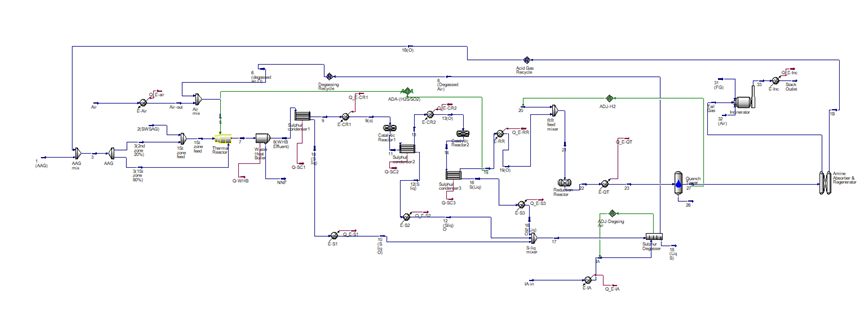
A refinery plant in the middle east started its official production in 2020. All acidic gas from the refinery units is treated in the SRU plant. The SRU plant was simulated with Aspen HYSYS V.11 and many case studies were performed on the simulation to give a clear overview of the handling of SRU plants. The output from the plant simulation is shown in Figure 1.
Process Description
The Sulphur Recovery Unit (SRU) and Tail Gas Treatment Unit (TGTU) are designed to recover sulphur from Amine Acid Gas and Sour Water Stripper Acid Gas. The SRU plant is composed from different sections. The SRU feed characteristics are shown in Table 1.
| Stream Description | Amine Acid Gas | Sour Water Stripper Acid Gas | |
|---|---|---|---|
| Property | Unit | Industrial | Industrial |
| Temperature | °C | 55 | 92 |
| Pressure | Kg/cm² g | 0.75 | 0.77 |
| Flow | kg/h | 11975 | 3674 |
| Component | Mole fraction | ||
| H 2 | 0.003 | 0.000 | |
| H O 2 | 0.083 | 0.339 | |
| H S 2 | 0.912 | 0.334 | |
| CH 4 | 0.001 | 0.000 | |
| NH 3 | - | 0.327 |
Table 1: Sulphur recovery unit feed characteristics.
Claus Section
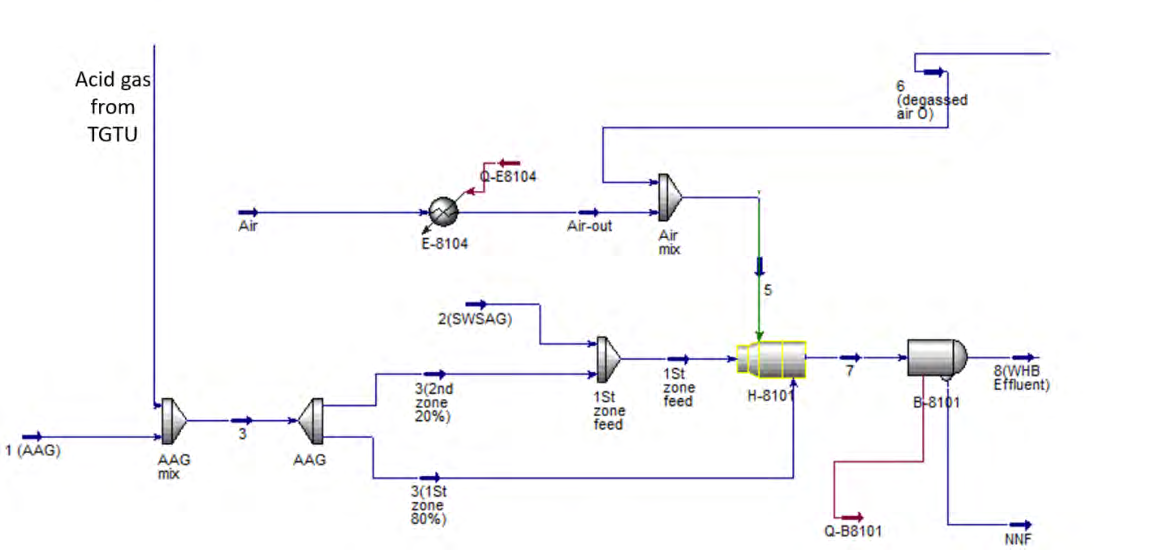
Claus section consists of Thermal Claus Section & Catalyst Claus section. The Claus process is used on acid gas streams containing essentially H2S and CO2.The concept of the process is that one third of the H2S contained in the acid gas feed is transformed to SO2 in the Thermal Claus Section. SO2 reacts with the remaining two third of H2S to form sulphur in the Catalyst Claus section. Thermal Reactor: The SWS Acid Gas is fed to the Main Burner of the Thermal Reactor with part of the Amine Acid Gas and the totality of combustion air. The complement of Amine Acid Gas is fed to the second zone of the Thermal Reactor, in order to maintain a minimum flame temperature in the first zone ensuring the NH3 complete destruction. The flame temperature of the first zone is expected to be in the range between 1350°C and 1450°C adiabatic NH3/ (H2S+ NH3) ratio. The air to the Main Burner is exactly sufficient to accomplish the complete oxidation of all hydrocarbons and ammonia present in the total feed gases and to burn as much H2S as required to obtain an (H2S/SO2) ratio equal to 2:1 in the tail gas from Claus. The thermal reactor with WHB is shown in Figure 2.
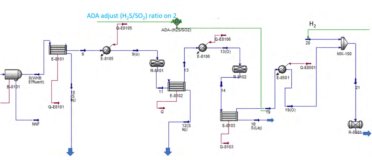
First and Second Claus Reactors: Before entering the Claus reactor, the process stream is indirectly heated to the optimum temperature for the catalytic conversion (about 240°C) in the first Reactor Reheater by means of high- pressure steam from Claus WHB. The reaction between H2S and SO2 in the Claus Reactor is accomplished till equilibrium over a catalyst bed; due to the exothermic reactions the gas leaving the Claus reactor has a temperature of about 300 °C. About 90% of the first Claus Reactor is filled with titanium (Ti) catalyst which enhances the hydrolysis reaction of COS and CS2. The effluent gas from the first Claus Reactor is then routed to the second Sulphur Condenser where the Sulphur is condensed and drained via a Sulphur seal to the relevant Sulphur Drum. The process gas flow from the second Sulphur Condenser is again reheated by HP steam up to 200°C and fed to the second Claus Reactor, loaded with alumina catalyst. Approaching the turndown condition, it is suggested to raise preheating temperature at about 207°C in order to keep outlet tail gas slightly above the Sulphur dew point. The gas leaving the second Reactor enters the Final Sulphur Condenser before being sent to the TGT section. Figure shows the Figure 3.
Tail Gas Treatment Unit TGTU
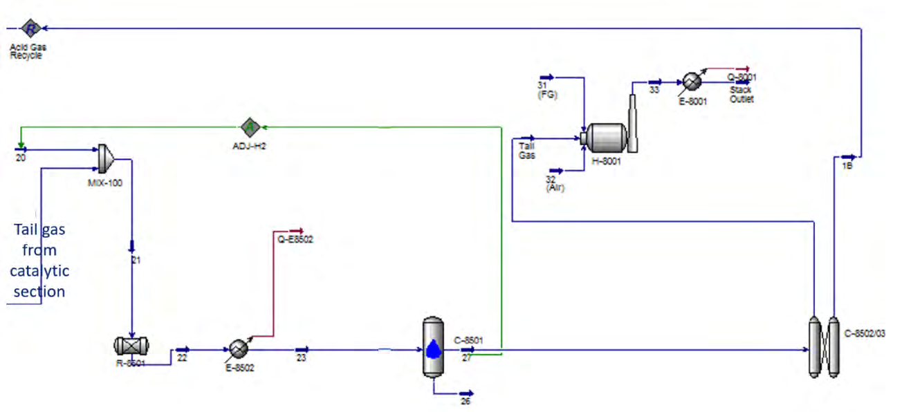
Tail gas from the SRU shall be further treated in a single tail gas treating unit (TGTU) to improve the H2S conversion to sulphur to 99.5wt%. Treat Claus tail gas from Claus section to convert SO2 into H2S. The converted H2S is cooled and then absorbed by lean amine then recycled to SRU feed to reprocessing. The tail gas treatment section is shown in Figure 4.
Degassing Section
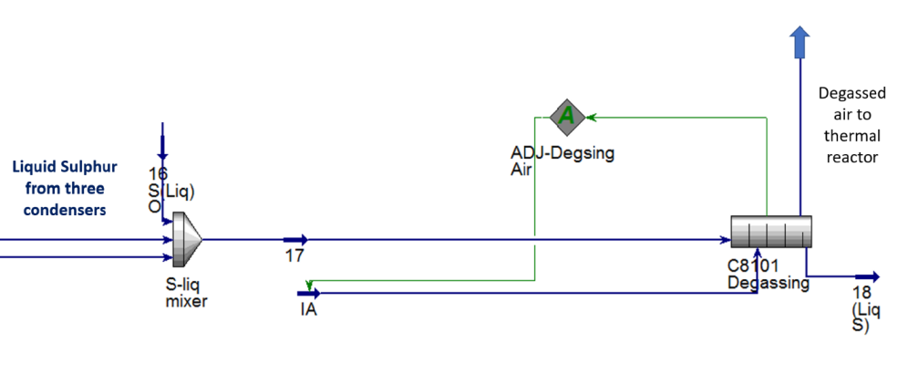
The liquid sulphur produced in the SRU contains soluble H2S and H2Sx (hydrogen polysulphides). during sulphur conveyance and handling the presence of H2S in the liquid could cause safety and environmental problems due to its toxicity and explosion hazards. Therefore, liquid sulphur is degassed in order to reduce the H2S content at the safety value of 10 ppm by weight. Figure 5 shows the degassing section.
Solidification Section
The degassed liquid sulphur is pumped to the Sulphur Solidification Section. The liquid sulphur supplied to the solidification unit is solidified according to the pastillation process, which foresees rotating machines providing liquid droplets to be solidified onto steel belts by means of closed loop circulating cold water. The solid pastilles/granules are collected with a collecting conveyor and lifted by a bucket elevator and a reversible conveyor into two silos. From the silos the sulphur pastilles are loaded directly onto the truck.
Incineration Section
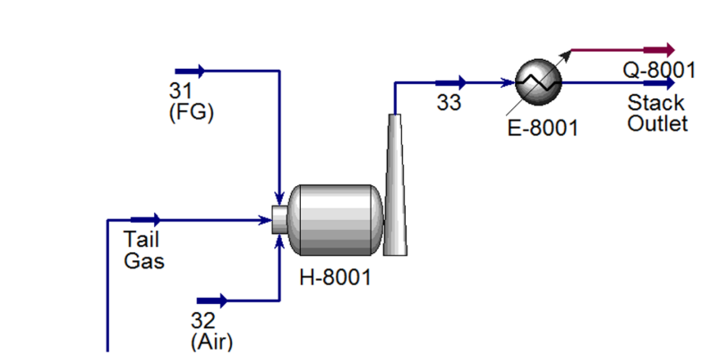
The incineration of the tail gas produced in the Claus and TGT units is necessary to transform all sulphured compounds present into SO2. The flue gas produced in the incineration is discharged to the atmosphere via a stack. Tail gas ignition temperature is much higher than the actual tail gas temperature, as all the fuel components in it present are at very low concentrations; therefore, tail gas combustion has to be supported by natural gas combustion. The Incineration combustion chamber temperature is of 650°C during normal operation. This temperature is necessary to assure the nearly complete combustion of H2S (less than 10 ppm residual H2S is expected) and of other sulphur compounds contained in the tail gas. Figure 6 shows the incineration section.
Materials and Methods
Simulation Step
The study used Aspen HYSYS V.10 Sulphur SULSIM package for plant simulation. The simulation then was validated by comparison with plant data and then used in case studies.
Simulation Sections
The simulation consisted of different sections: (Claus, TGTU, degasser section and incinerator) sections.
Simulation of Claus Section: The reaction furnace empirical model is selected NH3 SWS Acid Gas (Legacy): This is a legacy model commonly used for a plant that processes a sour water stripper (SWS) acid gas that contains significant amounts of ammonia (SWS acid gas stream contains 33% mole fraction ammonia), furnace type is selected two- chambers, other empirical models as (rich feed acid gas (legacy), lean feed acid gas (legacy), oxygen enrichment (legacy), straight through amine acid gas, SWS acid gas, split flow with lean acid gas, oxygen enrichment all acid gas, co-firing amine acid gas, co-firing SWS acid gas) are not suitable for this case. The 2 catalytic reactors are selected as catalytic converters, the three Sulphur condensers are selected as Sulphur condensers. Sulphur condensers required information for definition are the inlet and outlet (temperatures and pressures). The catalyst selected in catalytic reactor1 is Titania catalyst. An ADA (Air Demand Analyzer) is controlling air flow to thermal reactor to adjust (H2S/SO2) in tail gas from catalytic section third condenser at a ratio of (2:1) as the optimum ratio for Sulphur conversion.
Simulation of Tail Gas Treatment Section (TGT): The tail gas treatment selected equipment is: (a quench tower, a simple amine absorber and regenerator. The reduction reactor is selected as hydrogenation bed. The hydrogen flow to reduction reactor adjust the hydrogen mole fraction outlet from the quench tower at a value of 0.2 mole fraction by an (adjust block). Recycle block is used for acid gas recycle from amine absorber and the regenerator to reaction furnace.
Simulation of Degasser and Incinerator: Degasser equipment is selected as (degassing), degasser outlet liquid Sulphur H2S content of 10 ppm by weight is defined. Incinerator equipment is selected with the exact name in HYSYS. Incinerator target exit temperature is 652oC, target outlet O2 mole fraction is 0.02. The defined parameters to the incinerator are tail gas, air and fuel gas inlet temperatures and pressures. A validation done for based case using industrial data to prove its ability to handle different situations.
Validation Step
Validation is done by comparing industrial data with simulation results. First, from the overall recovery efficiency point of view. Second, comparing between base case simulation and industrial data, the comparison concentrates on outlet product Sulphur stream and flue gases from stack stream because the aim of the plant is Sulphur production achieving environmental regulations. Third, outlet temperatures from reactors producing Sulphur (reaction furnace, catalytic reactor1 and catalytic reactor2) as they are a good indication about the performance of the reactors. The validation shows the simulation ability to handle plant test performance and process optimization efficiently. The validation results are shown in Table 2.
| Stream Description | Liquid Sulphur Product | Flue Gas to Stack | |||||
|---|---|---|---|---|---|---|---|
| Property | Unit | Industrial | Simulation | % Error | Industrial | Simulation | % Error |
| Temperature | °C | 135 | 135 | - | 652 | 652 | - |
| Pressure | kg/cm² g | 0.01 | 0.01 | - | 0.01 | 0.01 | - |
| Flow | kg/h | 12430 | 12438 | 0.1 | 41283 | 43002 | 4.2 |
| Component | Mole fraction | ||||||
| H 2 | 0.000 | 0.000 | 0.0 | 0.012 | 0.011 | 8.3 | |
| H O 2 | 0.000 | 0.000 | 0.0 | 0.116 | 0.120 | 3.6 | |
| CO | 0.000 | 0.000 | 0.0 | 0.000 | 0.000 | 0.0 | |
| N 2 | 0.000 | 0.000 | 0.0 | 0.828 | 0.819 | 1.0 | |
| O 2 | 0.000 | 0.000 | 0.0 | 0.020 | 0.020 | 1.4 | |
| CO 2 | 0.000 | 0.000 | 0.0 | 0.025 | 0.023 | 5.3 | |
| S liq | 1.000 | 1.000 | 0.0 | 0.000 | 0.000 | 0.0 | |
| NH 3 | 0.000 | 0.000 | 0.0 | 0.000 | 0.000 | 0.0 |
Table 2: Validation results.
Results and Discussions
Effect of Decreasing Combustion Air Outlet Temperature on the Thermal Reactor
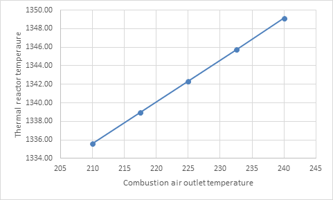
The combustion air is responsible to perform all the oxidation reactions in the thermal reactor. The design air temperature inlet to the thermal reactor is 240 oC. A case study is performed to see the effect of decreasing this temperature on thermal reactor parameters. The reactor temperature decreased from 1349.12 oC to 1335.61 oC. Consequently, the concentration of by-products COS and CS2 increased. Table 3 shows the Effect of decreasing combustion air outlet temperature on the thermal reactor. The COS concentration increased from 6.14 ppm-mol to 7.83 ppm- mol. The CS2 concentration increased from 7.10 ppm-mol to 8.50 ppm-mol. The Sulphur conversion decreased from 69.09% to 69.05%.
| Combustion Air T (Oc) | Thermal Reactor Outlet T (Oc) | Thermal Reactor Sulphur Conversion % | Thermal Reactor COS ppm-mol Outlet | Thermal Reactor CS 2 ppm-mol Outlet |
|---|---|---|---|---|
| 210 | 1335.61 | 69.05 | 7.83 | 8.5 |
| 217.5 | 1338.97 | 69.06 | 7.41 | 8.13 |
| 225 | 1342.34 | 69.07 | 6.99 | 7.77 |
| 232.5 | 1345.72 | 69.08 | 6.56 | 7.43 |
| 240 | 1349.12 | 69.09 | 6.14 | 7.1 |
Table 3: Effect of decreasing combustion air outlet temperature on the thermal reactor.
Figure 7 shows Effect of decreasing combustion air outlet temperature on the thermal reactor burner temperature.
- Effect of Decreasing Catalytic Reactor 1 Inlet
- Temperature
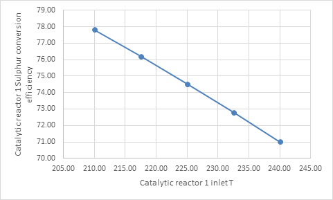
- The decreasing of catalytic reactor 1 inlet temperature from 240oC to 210oC decreases the hydrolysis reaction of
- COS from 99.04% to 98.34% and decreased CS2 hydrolysis
- Catalytic Reactor 1
- Inlet T (Oc)
- Catalytic Reactor 1 COS
- Hydrolysis Result %
- Catalytic Reactor 1 CS2
- Hydrolysis Result%
- Catalytic Reactor 1 Sulphur
- Conversion Efficiency%
- 210
- 98.34
- 86.88
- 77.82
- 217.5
- 98.6
- 88.71
- 76.2
- 225
- 98.79
- 90.26
- 74.52
- 232.5
- 98.94
- 91.57
- 72.79
- 240
- 99.04
- 92.67
- 71.02
Table 4: Effect of decreasing Catalytic reactor 1 inlet temperature.
Figure 8 shows the decrease of Sulphur conversion efficiency by the higher temperatures.
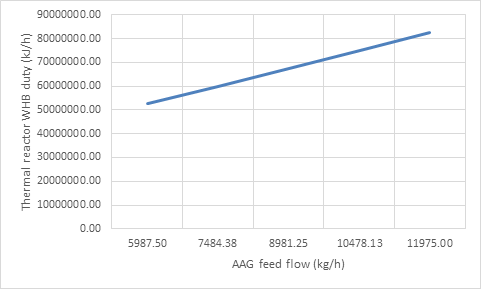
Effect of decreasing the AAG feed to the thermal reactor on the WHB duty
Decreasing the AAG feed to the thermal reactor decreases
| AAG Feed Mass Flow (kg/h) | WHB duty (kJ/h) |
|---|---|
| 5987.5 | 52587827 |
| 7484.38 | 60003631 |
| 8981.25 | 67459477 |
| 10478.13 | 74914338 |
| 11975 | 82301625 |
Table 5: Effect of decreasing AAG feed to thermal reactor on thermal reactor WHB duty.
the WHB duty from 82301625.34kJ/h to 52587827.42 kJ/h as shown in Table 5. This means that steam production from the WHB will be decreased also.
Figure 9 shows this relation.
Summary and Conclusions
A Sulphur recover unit of a refinery plant was simulated using a special HYSYS package named SULSIM. The results were validated and compared with industrial data. Then case studies are performed to understand the SRU performance. decreasing combustion air outlet temperature on the thermal reactor from 240 oC to 210 oC decreases the thermal reactor burner temperature from 1349.12 oC to 1335.61, increases the concentration of COS by-product from 6.14 ppm-mol to 7.83 ppm-mol, increases the concentration of COS by-product from 7.10 ppm-mol to 8.50 ppm-mol and decreases the Sulphur conversion from 69.09% to 69.05%. Decreasing catalytic reactor inlet temperature from 240 oC to 210 oC decreases the hydrolysis reaction of COS from 99.04% to 98.34%, decreases CS2 hydrolysis from 92.67% to 86.88% but increases the Sulphur conversion efficiency increased from 71.02% to 77.82% because the Claus reaction performance is better on lower temperatures. Decreasing the AAG feed to the thermal reactor from 11975.00 kg/h to 5987.50 kg/h decreases the thermal reactor WHB duty from 82301625.34 kJ/h to 52587827.42 kJ/h.
References
-
Khatami A, Heidari Y, Safadoost A, Aleghafouri A, Davoudi M (2016) The activity loss modeling of catalytic reactor of sulfur recovery unit in South Pars Gas Complex (SPGC) 3rd refinery based on percolation theory. Journal of Natural Gas Science and Engineering 28: 723-736.
-
Mahmoodi B, Hosseini SH, Ahmadi G, Raj A (2017) CFD simulation of reactor furnace of sulfur recovery units by considering kinetics of acid gas (H2S and CO2) destruction. Applied Thermal Engineering 123: 699- 710.
-
Lavery CB, Marrugo-Hernandez JJ, Sui R, Dowling NI, Marriott RA (2019) The effect of methanol in the first catalytic converter of the Claus sulfur recovery unit. Fuel 238: 385-393.
-
Ibrahim AY, Ashour FH, Gadallah MA (2021) Exergy Study of Amine Scrubber Unit of a Sulphur Recovery Plant using Methyl Diethanolamine: A Real Starting up Plant. Petroleum and Coal 63(1): 155-165.
-
Ibrahim AY, Ashour FH, Gadallah MA (2021) Exergy Study of Amine Regeneration Unit Using Diethanolamine in a Refinery plant: A Real Start-Up Plant. Heliyon 7(2): e06241.
-
Abdoli P, Hosseini SA, Mujeebu MA (2019) Effect of Preheating Inlet Air and Acid Gas on the Performance of Sulfur Recovery Unit-CFD Simulation and Validation. Forschung im Ingenieurwesen 83(1): 81-89.
-
Sui R, Lavery CB, Li D, Deering CE, Chou N, et al. (2019) Improving low-temperature CS2 conversion for the Claus process by using La (III)-doped nanofibrous TiO2 xerogel. Applied Catalysis B: Environmental 241: 217- 226.
-
Ibrahim S, Rahman RK, Raj A (2017) Effects of H2O in the feed of sulfur recovery unit on sulfur production and aromatics emission from Claus furnace. Ind Eng Chem Res 56(41): 11713-11725.
-
Hosseini SM, Alizadeh R, Alizadehdakhel A, Behjat Y, Nooriasl P (2019) Enhancement of gas distribution uniformity in a claus process catalytic reactor using computational fluid dynamics. Chemical Engineering and Processing-Process Intensification 144: 107653.
-
Rostami A, Tavan Y (2019) A survey on exergy, energy and environmental analysis of sulfur recovery unit in case of five intensified configurations. Chemical Papers 73(6): 1529-1539.
-
Kazempour H, Pourfayaz F, Mehrpooya M (2017) Modeling and multi-optimization of thermal section of Claus process based on kinetic model. Journal of Natural Gas Science and Engineering 38: 235-244.
-
Sui R, Lavery CB, Li D, Deering CE, Chou N, et al. (2019) Improving low-temperature CS2 conversion for the Claus process by using La (III)-doped nanofibrous TiO2 xerogel. Applied Catalysis B: Environmental 241: 217- 226.
-
Mehmood A, Alhasani H, Alamoodi N, AlWahedi YF, Ibrahim S, et al. (2020) An evaluation of kinetic models for the simulation of Claus reaction furnaces in sulfur recovery units under different feed conditions. Journal of Natural Gas Science and Engineering 74: 103106.
-
Ghahraloud H, Farsi M, Rahimpour MR (2017) Modeling and optimization of an industrial Claus process: Thermal and catalytic section. Journal of the Taiwan Institute of Chemical Engineers 76: 1-9.
- Nigeria’s Vulnerability in the Face of Global Energy Policy
- A Simulation Study of Investigation of Optimum Oil Production Performance by Applying Various Gas Injection Methods in Oil Reservoir
- Characterization of Permo-Triassic Reservoirs through Thermal Maturity Assessment of Westphalian Source Rocks in the Cheshire Basin
- Influence of Microwax on the Rheological and Thermal Behaviour of a Wax Crude Oil
- Real-Time Monitoring and Performance Optimization of Steam Injection in Heavy Oil Reservoirs Using Fiber Optic Sensing and Integrated Predictive Simulation Models
- Rapid On-Site Determination of the Total Petroleum Hydrocarbon Content of Soils by Handheld Fourier Transform Near-Infrared Spectroscopy: Development of a Global, Site- and Scanner- Independent Calibration Model