Acid Gas Injection into Petroleum Reservoirs: A Review
Matrix acidizing using acid gases is an under developed phenomenon in the oil and gas industry. For most petroleum engineers the most common acid gases are carbon dioxide (CO2) and dihydrogen sulfide (H2S). CO2 is mostly injected into oil reservoirs to achieve full/partial miscibility with the crude oil. In the process, CO2 reacts with formation water to form carbonic acid (a weak acid). Many research papers discuss how carbonic acid reacts with carbonate minerals and causes dissolution. Another popular acid gas in the oil industry is H2S. H2S is produced as an associated/dissolved gas in crude oil. H2S has the ability to react with formation water to form hydrosulfuric acid (a weak acid). This research paper introduces other acid gases that react with formation water and generate strong acids. These gases are: Sulfur Trioxide (SO3), Nitrogen Dioxide (NO2), Hydrogen Chloride (HCl), Hydrogen Bromide (HBr) and Hydrogen Iodide (HI). It is understood that most reservoirs are water wet or intermediate wet. Acid gas injection would change the pH of the water film around the oil globule in the pore. pH of the water in most reservoirs typically ranges between 5.5 and 8.5. Lowering the pH of the water that coats the pore, will initiate the acid treatment and reduce the presence of carbonates within the rock. This would result in an increase in porosity and permeability within the reservoir. Some visual examples of stimulating the reservoirs using acid gases are also discussed in this research paper. Acid gas injection would be considered a solution to many issues in our reservoirs. It would allow for recovery from vuggy pores (also known as isolated pores) in carbonate formations. It would also enhance unconventional reservoirs such as shale oil reservoirs (knowing that some of those shale oil reservoirs have higher carbonate content). Furthermore, in our conventional reservoirs we produce from the larger pores leaving behind a lot of oil in tight pores, acid gas injection would open up some of those tight pores. Acid gas is matrix acidizing tool, that petroleum engineers need to enhance the reservoir rock properties.
Introduction
Acid gas is defined as a gas that would react or dissolve in water to produce an acid. There are five acid gases that are chosen to be analyzed in this research paper. The five acid gases are: SO3, NO2, HCl, HBr and HI. Note, HCl is the gas that reacts with water to produce the liquid form hydrochloric acid.
The five gases selected for analysis, in this research paper, satisfy the following criteria:
- The gases would react with water in anerobic conditions (without the need of oxygen) to produce acid. This is because our reservoirs are naturally operating in an anerobic state.
- The five gases, would not react directly with steel. Downhole completion systems include casings and tubings, that are made of low-alloy steel. Low-alloy steel typically contains iron, carbon, manganese, chromium, nickel and molybdenum. A number of industrial corrosion manuals, research papers, and books have shown that the corrosion effect of acid gases on various steel alloys are minimal (even at elevated temperature such as > 500oF) [1, 2]. This would prevent a direct reaction with the downhole completion equipment. Therefore, during an injection/shut-in period, acid gas injection would be considered a robust system. Note, these acid gases would react with moisture on the steel to create acid, and initiate corrosion. Nonetheless, this effect can be reduced and could be discussed in future research material.
- Acid gases that would react with water in the reservoir to produce a strong acid.
A strong acid is necessary to ensure an optimal matrix acidizing job.
Most of these molecules are very small in size, granting them access to our least permeable formations such as shale oil reservoirs. They are generally not known to react with steel, which means they will not react with the downhole completion equipment during the injection and shut- in period. A shut-in period is important to allow for two reactions to occur. The first reaction is for the acid gas to react with the formation water. The second reaction is to allow the generated acid to dissolve some of the carbonates. A shut-in period would also allow the acid generated to lose its power to the rock and not the wellbore. Although it is good practice to try and lose the power of the acid to the reservoir rock, this cannot be a reliable solution for all reservoirs. Therefore, it would be important to find a reliable corrosion protection system in the long run. Knowledge obtained from this research paper should only be used complementary to field results and experimental work.
Strong Acids
By definition, strong acids dissociate completely in water to give the maximum number of hydrogen ions [3]. The following table shows the list of strong acids:
| Name of Acid | Formula | Ionization |
|---|---|---|
| Hydroiodic Acid | HI | H+ + I- (aq) (aq) |
| Hydrobromic Acid | HBr | H+ + Br- (aq) (aq) |
| Perchloric Acid | HClO 4 | H+ + ClO - (aq) 4(aq) |
| Hydrochloric Acid | HCl | H+ + Cl- (aq) (aq) |
| Sulfuric Acid | H SO 2 4 | H+ + HSO - (aq) 4(aq) |
| Nitric Acid | HNO 3 | H+ + NO - (aq) 3(aq) |
All the acids in Table 1, have one thing in common, they dissociate completely in water to give a hydrogen ion (H+). Hydrogen ions are actually bound to water molecules in the solution and they form hydronium ions (H3O+). Nonetheless, both representations are acceptable as long as we understand that the protons are transferred in the form of hydronium ions in the solution.
Acid-Base Reaction
In 1923, BrØnsted JN and Lowry TM defined acid-base reactions in terms of the transferring of hydrogen ions from one substance to another. Their definition of acid-base reaction is: an acid is a substance, like hydrochloric acid, that would dissolve in water to produce hydrogen ions. While a base is a substance that would accept a proton (in some cases the accepted proton is in the form of a hydrogen ion) [3]. Rock dissolution in our reservoirs is a classical acid- base reaction, where the carbonate rocks are the base in the reaction. Acids such as carbonic acid and those mentioned in table 1 have the ability to dissolve the carbonate minerals in our reservoirs. However, strong acids will outperform weaker acids, such as carbonic acid. This is because strong acids produce the maximum number of hydrogen ions in water, and hydrogen ions are the prime factor that cause rock dissolution (carbonate rocks specifically).
For example, limestone is primarily composed of calcium carbonate (CaCO3). When CaCO3 is exposed to an acidic solution, the hydrogen ions in the acid replace the Calcium ions (Ca2+). The hydrogen ions also form new bonds with the carbonate ions (CO3 2-), resulting in the formation of H2O and CO2 molecules. This example can be translated into the following chemical reaction between sulfuric acid and CaCO3 [3]:
Calcium Carbonate Sulfuric Acid Calcium Sulfate Water Carbon Dioxide CaCO H SO CaSO H O CO + → + + (1) s aq s l g ( ) ( ) ( ) ( ) ( ) ( ) ( ) ( ) ( ) ( )
3 2 4 4 2 2
Note, this reaction would occur in a similar manner between all the acids mentioned in Table 1 and CaCO3. Other carbonate rocks such as dolomite would exhibit a similar reaction with strong acids. The reactions between the acidic solutions created and carbonate rocks are gaseous reactions. In the reservoir, these gaseous reactions would have a similar effect to solution gas drive. In the case of acid gas injection, it would be called reaction gas drive.
The Reactions of Acid Gases with Water
The five acid gases mentioned at the beginning of this research paper react with water in anerobic conditions to produce a strong acid. The following are the five reactions of the five acid gases, mentioned earlier, with water [3, 4].
Sulfur Trioxide Water Sulfuric Acid SO H O H SO + → (2)
g l aq ( ) ( ) ( ) ( ) ( ) ( )
3 2 2 4 Nitrogen Dioxide Water Nitrous Acid Nitric Acid NO H O HNO HNO + → + (3)
2 g l aq aq ( ) ( ) ( ) ( ) ( ) ( ) ( ) ( )
2 2 2 3 ( ) ( ) ( ) ( ) ( )
H O l
Hydrogen Chloride Hydrogen Ion Chloride Ion HCl H Cl + − → + (4)
2 ( ) ( ) g aq aq ( ) ( ) ( ) ( ) ( )
H O l
Hydrogen Bromide Hydrogen Ion Bromide Ion HBr H Br + − → + (5)
2 ( ) ( ) g aq aq ( ) ( ) ( ) ( ) ( )
Hydrogen Iodide Hydrogen Ion Iodide Ion HI H I + − → + (6)
H O l
2 ( ) ( ) g aq aq The reactions shown above, (2) to (6), all show strong acids as a final product. Nitrous acid is not a strong acid however, it is a product of a reaction between NO2 and water as shown in reaction (3). One could state that the reaction between NO2 and water, produces a 1:1 mixture of a strong acid and weak acid.
Lewis Structure & Formal Charges of the Five Acid Gases
This section was created in an effort to determine which of the five acid gases is less likely to alter the chemistry of the crude oil. The idea is to inject acid gas into the oil reservoir and change only the formation water in the pore to an acidic solution. The Lewis Structure of chemicals illustrates the construction of the substance and is a fundamental concept in chemistry. The following table demonstrates the Lewis Structure of the five acid gases:
| Lewis Structure | |
|---|---|
| Nitrogen Dioxide (NO2) | Chemical structure of Nitrogen Dioxide |
| Sulfur Trioxide (SO3) | Chemical structure of Sulfur Trioxide |
| Hydrogen Chloride (HCl) | Hydrogen Chloride structure |
| Hydrogen Bromide (HBr) | Hydrogen Bromide structure |
| Hydrogen Iodide (HI) | Hydrogen Iodide structure |
Table 2: Lewis Structure of Acid Gases.
$$ \mathrm {O} _ {2} ^ {+} \mathrm {N} ^ {-} \mathrm {O} _ {2} ^ {-} $$
Notice that NO2’s Lewis structure is drawn with charges on the nitrogen and one of the oxygen atoms. This is a result of the implementation of the Bohr Model, Octet Rule, and the calculation of the Formal Charges of each atom. The Lewis Structure of the NO2 molecule represented in Table 2 is statistically the most probable assembly, because the total molecular charge is closest to zero. Molecules with formal charges are known for their reactive nature, in comparison with those that have no formal charges and are understood to be stable molecules. NO2 is the molecule that is most likely to alter the chemistry of crude oil. Analyzing this concept from another perspective, it is understood that crude oil is a very complex substance (composed of solids, liquids and gases), that requires multiple refining stages to separate its contents. One could also state that NO2 is the acid gas that is least likely to exit the reservoir in its original form. These characteristics could serve well in reservoirs that would have a small depth of invasion (DOI) such as shale oil reservoirs.
Advantages of Acid Gases in our Reservoirs
Acid gas injection will deliver a number of matrix stimulation advantages. Some of those advantages include:
- Firstly, acid gas will increase porosity and permeability in our reservoirs. When acid starts to dissolve some of the carbonates in the reservoir, it will increase permeability and improve flow within the reservoir.
- Secondly, the acid formed in the reservoir will be a strong and concentrated acid, though this will depend entirely on the amount of acid gas injected. When compared to our conventional acid stimulation jobs, one would find that for decades we used diluted acids to reduce the damage done to the wellbore during the injection period [5]. In this case acid gas will bypass the completion system downhole and form acid in the reservoir rock.
- Thirdly, acid gases will flow into the smallest pore throats due to our principle understanding that gases expand in our reservoirs. Our conventional matrix acidizing tools are all in liquid form. Liquids are notorious for forming channeling/fingering flow patterns in our reservoirs. This effect can be neglected with acid gas injection.
- Fourthly, acid gases can serve as a possible remedy for hydraulic fracturing failures.
For example, acid gas can convert trapped hydraulic fracturing fluid, which in most cases is primarily water, to an acidic solution. The acid created can dissolve the carbonates at the fracture wall, liberating trapped hydrocarbons.
Immobility of Formation Water
Some of the formation water remains trapped in the reservoir pores due to a number of principles that we have developed over the years. In the case of a water wet rock, some of those principles include: 1. Interfacial tension between the solid phase and the liquid phase. This tension is understood to reduce the mobility of the water within the pore [6]. 2. Capillary pressure which is the difference between the pressure of the non-wetting phase and the pressure of the wetting phase [6]. Capillary pressure in the pore is the net resultant pressure exerted by one fluid on the other. This phenomenon also contributes to the immobility of water in the pore. Immobile formation water is sometimes referred to as connate water. Understanding that water in the rock will not move easily and is likely to be converted to an acidic solution during an acid gas injection period is key.
Retraction of the Solid-Liquid Interface
This section will focus on two dimensional diagrams that portray the retraction of the solid-liquid interface, more specifically the interface of the carbonate minerals and the acidic solution created. The diagrams are not supposed to depict all the principles of petrology or the features observed in petrography. Instead, the target of these diagrams is to be able to visualize the possible changes on a pore/fracture scale due to an acid gas injection job. These changes will affect the flow characteristics within the reservoir. For example, Figure 1 below shows a reduction in calcite grain size:
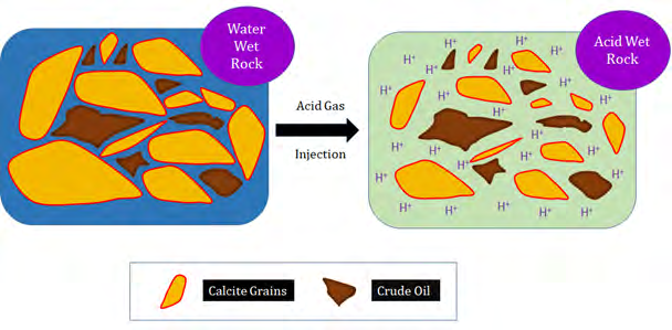
Figure 1 presents an example of the retraction of the solid-liquid interface. The Solid-Liquid interface in Figure 1 is denoted by the red line. Note, acid gas injection would cause an enlargement of the pore throat and result in an improvement in the flow within the reservoir. An increase in the pore throat size translates to an increase in the overall permeability of the reservoir. Moreover, it is possible that acid gas injection could prove to be a system that would increase effective porosity, while reducing tortuosity.
The strong acid generated in the reservoir should be given sufficient time to lose its power to the rock and not the wellbore or surface equipment. Also, there are ways to control acid gases that could be produced along with the oil and those could be discussed in other research papers. Acid gas injection would work well in conventional reservoirs that have water invasion. Water invasion could occur naturally (in the presence of an active aquifer), or artificially (in the application of water flooding techniques). Continual water invasion into the oil zone would allow for more acid to be generated and possibly lead to an increase in recovery factor.
Furthermore, in some unconventional reservoirs we resort to hydraulic fracturing as a reservoir stimulation method. Most hydraulic fracturing fluids are composed primarily of water. Much of the fracturing fluids remains trapped in the reservoir. If this fluid can be converted into an acidic solution, the resulting acidic solution can be used as a fracture enhancement tool. Take for example, Figure 2 below:
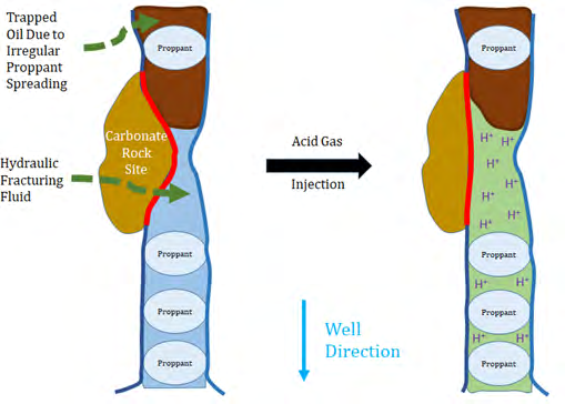
Figure 2 above shows another example of the retraction of solid-liquid interface. The red line in figure 2 is retracting due to acid gas injection. Notice that oil is originally trapped in the fracture due to uneven proppant spreading. Etching the fracture wall would lead to fracture enhancement and release more hydrocarbons (crude oil). Note, the acid created within the hydraulic fractures will not dissolve the proppants, because in most cases the proppant used is basically sand (quartz). Therefore, acid gas injection will not close the man-made fractures. Any connected pore system, such as tight pores or natural fractures, attached to the hydraulic fracture wall could also be enhanced to allow for more oil recovery. There are many ways that acid gases could be used to enhanced our reservoir rock properties. Only a couple were discussed in this research paper.
Conclusion
Acid gases have been in use for many years in different industries across the globe. These industries have been successful in controlling those gases and eliminating any chances of air pollution. The oil and gas industry already has decades of experience in handling acid gases, especially when it comes to CO2 and H2S. Understanding that acid gases would provide petroleum engineers a number of advantages, is the first step to developing a petroleum production system that could handle those gases.
Some of the key advantages that acid gases provide to a petroleum engineer are:
- Increasing permeability and ability of fluids to flow within our reservoirs.
- Likely to increase effective porosity while reducing tortuosity.
- Avoid fingering/channeling flow patterns within our reservoirs, and therefore more pores are expected to be acidized.
- Ability to form a strong and concentrated acid within our reservoirs, without inflicting damage to our existing wellbore equipment.
- A possible remedy to hydraulic fracture failures.
Tools that create flow or permeability within our reservoirs are petroleum engineering tools. Acid gases will contribute to the future of the oil and gas industry, it is just a matter of time.
Funding
This research received no specific grant from any funding agency in the public, commercial, or not-for-profit sectors.
References
-
O’Neil MJ (2006) The Merck Index: An Encyclopedia of Chemicals, Drugs and Biologicals. 14th(Edn.), Merck Research Laboratories Division of Merck & Co., Inc, Whitehouse Station, USA.
-
Brown MH, DeLong WB, Auld JR (1947). Corrosion by Chlorine and by Hydrogen Chloride at High Temperatures. Ind Eng Chem 39(7): 839-844.
-
Averill A, Eldredge P (2014) General Chemistry: Principles, Patterns, Applications. Volume 1, Flat World Knowledge, Washington, USA.
-
Lovejoy ER, Hanson DR, Huey LG (1996) Kinetics and products of the Gas-Phase Reaction of SO3 with water. J Phys Chem 100(51): 19911-19916.
-
Economides MJ, Daniel Hill A, Ehlig-Economides C, Zhu D (2015) Petroleum Production Systems. 2nd (Edn.), Pearson Education Inc, Westford, USA, pp: 1-59.
-
Willhite GP (1986) Water Flooding. Society of Petroleum Engineers, Richardson, USA.
- Nigeria’s Vulnerability in the Face of Global Energy Policy
- A Simulation Study of Investigation of Optimum Oil Production Performance by Applying Various Gas Injection Methods in Oil Reservoir
- Characterization of Permo-Triassic Reservoirs through Thermal Maturity Assessment of Westphalian Source Rocks in the Cheshire Basin
- Influence of Microwax on the Rheological and Thermal Behaviour of a Wax Crude Oil
- Real-Time Monitoring and Performance Optimization of Steam Injection in Heavy Oil Reservoirs Using Fiber Optic Sensing and Integrated Predictive Simulation Models
- Rapid On-Site Determination of the Total Petroleum Hydrocarbon Content of Soils by Handheld Fourier Transform Near-Infrared Spectroscopy: Development of a Global, Site- and Scanner- Independent Calibration Model