Completion Design in Petroleum Well with Two Different Reservoirs
This paper proposes an economical and profitable completion method capable of producing in two different reservoirs of a well named "X" (for confidential reasons) in a single descent. The data used are pressure, volume and temperature (PVT), reservoir properties, well architecture, and drilling data. To achieve the desired objective, it is necessary to make the selection of materials, the operating pressures and temperatures, the choice of the appropriate completion design, the installation procedure, the nodal analysis, and finally, the economic balance sheet. Two completions of well X are considered; known as the single string completion, and the dual completion. The oil production flow rate of the well X after the single string completion is 5964.11 STB/D and the cost of equipment used for the single string completion design are 137,500 $. The oil production flow rate of the well X after the dual completion is 5700 STB/D and the cost of equipment used for the double completion design is 147,600 $. The appropriate completion for well X is the single string completion because it is less expensive and performs better in terms of gain and oil flow rate produced. The results obtained are hydrogenated nitrile (HNBR) as a sealing element, 258°F and 5500 PSI as pressure and operating temperature for the design of the single string completion. And the most appropriate type of design is the annular tubing completion. In this field named "Y" (for confidential reasons), the design of single string completion is made with the tubing of 3-1/2", weight of 10.2 ppf, a range of 30 ft and a hydro trip sup of 3-1/2". The financial component shows a return on investment from one year eight months.
Introduction
Hydrocarbons come from the decomposition of organic matter from plants and animals [1, 2, 3]. This organic matter is transported by the river and deposited at the bottom of the sea or large continental lakes, where hydrocarbons are formed [4, 5, 6]. They are located by seismic surveys, mainly by seismic reflection [7, 8, 9], and extraction begins with drilling to bring the hydrocarbons to the surface by installing a completion [10, 11, 12]. Given that the completion of a well is the interface between the reservoir and the surface equipment, it is impossible to create a well by drilling. It is impossible to produce a well safely and efficiently [13, 14, 15]. The increase in production from an oil well and the oil and gas reserves depend considerably on the process and type of completion [16, 17, 18]. Sometimes several reservoirs must be produced from a single well because it is more economical. A well may encounter several pools with different properties, notably petrophysical properties (permeability, porosity, saturation), mineralogical properties (sand, greasy sand, carbonates), and also different pressures and temperatures. In this case, the production method depends essentially on the type of completion [19, 20, 21]. This is the case with well X, which crosses two reservoirs, one open-hole and the other cased, with different pressures, mineralogical and petrophysical properties. Exploiting these reservoirs means finding a suitable completion.
The paper aims to design a completion for the well X with two reservoirs and this aim is to be achieved through the following specific objectives: Choice of the most appropriate completion method and the corresponding equipment; Design of the completion and the installation procedure; - Nodal analysis to see the performance of the completion; And the economic balance. To achieve the main objective of this paper, the study is divided into three sections. The first section offers the introduction. The second section presents the data, tools, methods, and results. The third section concludes everything.
Data, Methods, and Results
The well X comprises two different reservoirs. The first reservoir (case hole) is cased because it is unconsolidated and the second reservoir (open spot) is not cased because the reservoir is consolidated. During production, the cased zone must be perforated to allow fluid to flow from the reservoir to the bottom of the well. To achieve the objectives set, four types of data are used: Completion data, petrophysical data, PVT data and drilling data. These data are shown in Tables 1 to 4.
| Depth (ft) | External Diameter (inch) | Bottom diameter (inch) | Grade | |
|---|---|---|---|---|
| Production casing | 9500 | 9.625 | 8.425 | L80 |
| Liner | 950012700 | 7 | 5.92 | N80 |
| Open hole | 1270016000 | 8.5 |
Table 1: Well architecture.
| Pressure | Temperature | Surface of perforations | Hole depth | Permeability | Productivity index | |
|---|---|---|---|---|---|---|
| Reservoir 1 | 5000 psi | 230 °F | 7500 ft | 8500 ft | 500 md | 3.5 stb/d.psi |
| Reservoir 2 | 4500 psi | 235 °F | 80 md | 3.5 stb/d.psi |
Table 2: Reservoir data.
| Parameters | Values |
|---|---|
| Reservoir 1 | GOR=500 scf/stb ; B0=1.2, Water cut= 0 %, API= 38°U=1,2 cp; Water salinity= 20000 ppm. |
| Reservoir 2 | GOR=350 scf/stb ; B0=1.1, Water cut= 0 %, API= 30°U=1,25 cp; Water salinity = 25000 ppm; %CO2= 0,05; %H2S= 0,025. |
| Measured depth (ft) | True vertical depth (ft) |
| 0 | 0 |
| 7000 | 7000 |
| 7700 | 7600 |
| 8400 | 8000 |
| 9500 | 8300 |
| 10500 | 8300 |
| 11500 | 8300 |
| 11200 | 8300 |
| 11700 | 8300 |
| 12200 | 8300 |
| 12900 | 8300 |
| 13000 | 8300 |
| 14000 | 8300 |
| 15000 | 8300 |
| 16000 | 8300 |
| 16500 | 8300 |
Table 3: PVT Data.
The Power Drawn software, Prosper software, nodal analysis, and economic evaluation are used to attain the aim of this paper which is the proposed completion method capable to of producing in two different reservoirs of well X.
Metallurgy Selection, Seal Selection, Steel Selection, and Description of the Installation
The suitable elastomer in the sealing elements is hydrogenated nitrile (HNBR). The partial pressure of CO2 is 225 atm, and that of H2O is 125.5 atm. The recommended metallurgy for the design is P110 and Q125, which are standard steels, so there is no risk of corrosion. The pressure and temperature of the selected equipment are 5500 psi and 581°F, respectively. In the well X, the fluids in reservoirs 1 and 2 have different densities, so there are two possible options. The first option is to produce fluids from reservoirs 1 and 2, one in the annulus and the other in the tubing. The second option is to install two tubings where production occurs in the respective tubings. The two proposed well X completion designs are illustrated in Figure 1.
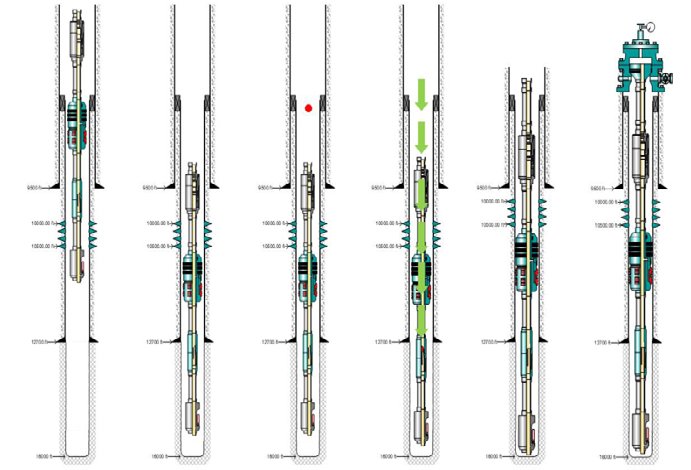
The numbers 1 to 4 shown in Figure 1 represent, respectively: The tubing, the packer, the ball, and the gauge. Figure 1(a) shows the single string completion of X well where production takes place in the annular space and the tubing. Figure 1(b) shows the double completion of X well, where production takes place in two tubings (short and long) with identical diameters. The completion running process of the production section is done in six steps, as shown in Figure 2.
(a) (b)
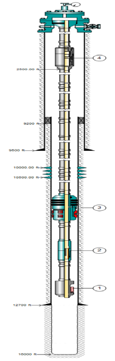
Figure 2 shows the steps in the installation procedure to be followed when installing the completion equipment for the well X, namely: - The first step is to install the top completion; - Lower the packer to depth and carry out the surface test; - Drop the chosen bale until it reaches the threshold; - Put pressure on the ball until it disappears to anchor the Packer; - Do the test to see if the packer held; - Increase the pressure further to shear the ball.
Assessing the Performance of Well X after Completion
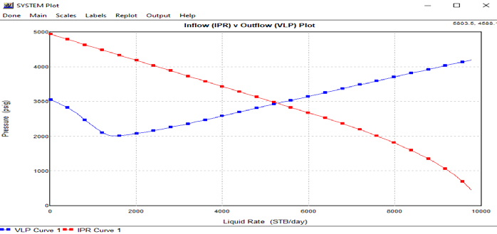
The results of simulations after the single string completion of well X are presented in Figure 3.
In Figure 3, reservoir 1 produces in the annulus separated from the second reservoir by the packer, and reservoir 2 produces in the production tubing. The blue curve represents the movement of the fluid from the bottom to the surface and the red curve represents the potential given by the reservoir. The intersection of the blue and red curves gives the optimum flow rate produced by the well X, 5964.11 STD/d. The results of simulations after the dual completion of well X are presented in Figure 4.
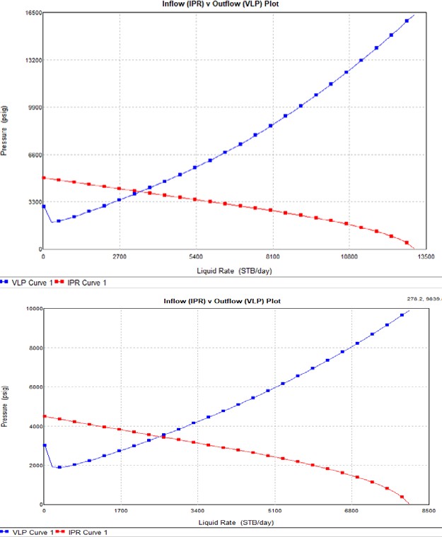
(a)
(b) Figure 4: Production simulations after the dual completion of well X: (a) Short tubing and (b) long tubing.
In Figure 4, production occurs in two tubings, with reservoir 1 producing in the short tubing and reservoir 2 in an open hole in the long tubing. The nodal analysis in well X through the short tubing gives a flow rate of 3200 STB/D with a head pressure of 300 PSI, as shown in Figure 4(a). The nodal analysis in well X for the long tubing gives a flow rate of 2500 STB/d with a head pressure of 300 PSI, as shown in Figure 4(b). The flow rate produced by well X is the sum of the two flow rates shown in Figure 4, which is 5700 STB/d.
Economic Evaluation
This subsection looks at the profitability of the project. To do this, it is necessary to determine the costs of the equipment used to carry out the two completions of well X and to establish the curve of the prediction of the production of well X, as well as the variation of the NPV as a function of time. For the single string completion of X well, the cost of equipment used is presented in Table 5.
| Equipment | Cost ($) |
|---|---|
| HTS, 3-1/2” | 10,000 |
| Packer 7” | 15,000 |
| GAUGE | 20,000 |
| BALL 2-7/8” | 1,000 |
| 433 TUBING 3-1/2, 10.2 ppf range 2 | 91,500 |
| Total cost ($) | 137,500 |
| HTS, 3-1/2” | 10,000 |
| Packer 7” | 15,000 |
| GAUGE | 20,000 |
| BALL 2-7/8” | 1,000 |
| Dual Packer 7” | 25,000 |
| 333 TUBING 2-7/8, 4.6 ppf range 2 | 33,300 |
| 433 TUBING 2-7/8, 4.6 ppf range 2 | 43,300 |
| Total cost ($) | 147,600 |
Table 4: According to Tables 5 and 6, single string completion of well X is less expensive than dual completion of well X. In add
For the dual completion of well X, the cost of equipment used is presented in Table 6.
According to Tables 5 and 6, single string completion of well X is less expensive than dual completion of well X. In addition, the single string completion of well X has a higher production rate of 264.11 STB/d than the dual completion of well X. The appropriate completion for well X is single string completion. The production prediction curve for well X after single string completion is shown in Figure 5.
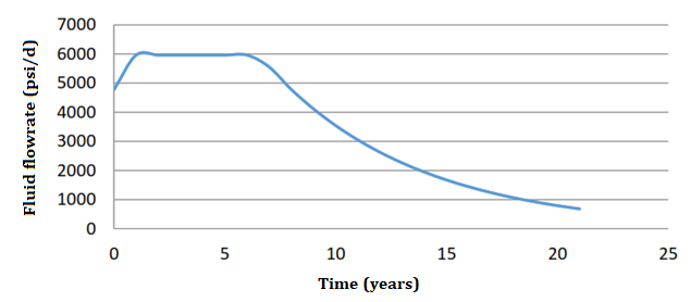
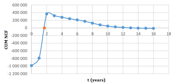
Figure 5 shows three phases: the growth phase, the constant phase, and the decline phase. The variation in NPV as a function of time for well X after single string completion is shown in Figure 6.
Figure 6 shows three phases. A negative phase during which the project is not yet profitable, a zero phase when total expenditure equals total revenue, and a growth phase representing profits. From one year and eight months onwards, the company recovers the money it would have spent and starts to make real profits from the second year onwards.
Conclusion
This paper aimed at proposing a feasible technical completion design that allows the isolation of the different fluids present in the two different reservoirs of well X. During production, it was found that the best materials were P110 and Q225 for metallurgy and hydrogen nitrile as elastomer. For this reason, the completion data, PVT data of the two different reservoirs of well X and drilling data were introduced into the Power Draw software and the Prosper software to obtain the following results: Single string completion design with a tubing, so production takes place in the tubing for the open hole reservoir and in the annulus for the tubed reservoir. Dual completion design with two production tubings (short and long) where two tubings have the same diameter; the short tubing was used to produce the tubed reservoir and the long tubing in the open-hole reservoir. The nodal analysis carried out in each completion was 5964.11 STB/D for the single string completion and 5700 STB/d for the dual completion. The cost of equipment used for the single string completion was 137,500 $ whereas the cost of equipment used for the dual completion was 147,600 $. The single string completion was chosen because it was less costly and gave a better return in terms of gain and throughput. For future work, it would be interesting to conduct gravel pack completion in the open-hole reservoir and acidification in the turbine-hole reservoir.
Conflict of Interest: The authors have nothing to disclose.
References
-
Miller RG, Sorrell SR (2013) The future of oil supply. Philos Trans A Math Phys Eng Sci 372(2006): 20130179.
-
(2014) Total, Formation of hydrocarbon deposits Planet energies, 20: 10-12.
-
Economides M(1994) Petroleum production systems. Prentice-Hall.
-
Alain M (2014) Geology and Geodynamics of Hydrocarbons. Encyclopedia of Energy 5: 11-15.
-
John S (2018) Forecasting Oil and Gas Producing for Unconventional Wells. 2nd (Edn.), Petro, Denver.
-
Economides MJ, Boney C (2000) Reservoir Stimulation in Petroleum Production (Reservoir Stimulation). John Wiley & Sons Ltd, Texas, Chinchester, USA.
-
Harry Jr (2017) Practical Petroleum Geochemistry for Exploration and Production. 1st (Edn.), Elsevier, USA.
-
Jahn F, Cook M, Graham M (2003) Hydrocarbon Exploration and production. 2nd (Edn.), Elsevier The Nertherlands, Amsterdam.
-
Cox DR, Newton AM, Huuse M (2020) An introduction to seismic reflection data: Acquisition, processing and interpretation. Regional Geology and Tectonics 1: 571- 603.
-
Guo B, Lyons WC, Ghalambor A (2007) Petroleum Production engineering a computer Assisted Approch.
-
John R, Richard L (2017) Introduction to petroleum engineering. Wiley, New Jersey.
-
Boyun G, William L, Ali G (2007) Petroleum Production Engineering, a computer-assisted approach. 1st(Edn.), Elsevier, Oxford.
-
Bellarby J (2009) Well completion design. 1st (Edn.), Elsevier, Amsterdam, Netherlands, pp: 304-367.
-
Fanchi JR, Christiansen RL (2016) Introduction to petroleum engineering. 1st (Edn.), John Wiley & Sons.
-
Foss B, Knudsen BR, Grimstad B (2018) Petroleum production optimization–a static or dynamic problem. Computers & Chemical Engineering 114: 245-253.
-
Renpu W (2011) Advanced Well Completion Engineering. 3rd (Edn.), Elsevier, Oxford, 33.
-
Rigtrain (2006) Drilling & Well Services Training; Well kill principles and procedures, Houston.
-
Crumpton H (2018) Well control for completions and interventions. 1st (Edn.), Oxford, Elsevier.
-
King G (1998) An Introduction to the basics of well completions, stimulations, and workovers. 1st (Edn.), Georges E. King, Tulsa.
-
Montrose R (2002) Completion Design Manual. 1st (Edn.), Aberdeen, UK.
-
Hernandez (2016) Fundamentals of Gas Lift Engineering: Well design and Troubleshooting. Elsevier Inc.
- Nigeria’s Vulnerability in the Face of Global Energy Policy
- A Simulation Study of Investigation of Optimum Oil Production Performance by Applying Various Gas Injection Methods in Oil Reservoir
- Characterization of Permo-Triassic Reservoirs through Thermal Maturity Assessment of Westphalian Source Rocks in the Cheshire Basin
- Influence of Microwax on the Rheological and Thermal Behaviour of a Wax Crude Oil
- Real-Time Monitoring and Performance Optimization of Steam Injection in Heavy Oil Reservoirs Using Fiber Optic Sensing and Integrated Predictive Simulation Models
- Rapid On-Site Determination of the Total Petroleum Hydrocarbon Content of Soils by Handheld Fourier Transform Near-Infrared Spectroscopy: Development of a Global, Site- and Scanner- Independent Calibration Model