Additive Prototyping in Dentistry- 3D Printing and Selective Laser Sintering
3D printing has been acclaimed as a disruptive technology which will change manufacturing of dental prosthesis. This technology is used in various fields such as aerospace, defense, art. Recently it has become a subject of great interest in virtual surgical planning. The technology has a particular resonance with dentistry. It has become of great importance with advancement in 3D imaging and modelling technologies such as CBCT, intraoral scanning and CAD CAM in dentistry. Uses of additive prototyping include the production of drill guides for dental implants, the production of physical models for prosthodontics, orthodontics and surgery, the manufacture of dental, cranio-maxillofacial and orthopedic implants and the fabrication of copings and frameworks for implant and dental restorations. This paper reviews the types of 3D printing technologies available and their various applications in dentistry and in maxillofacial surgery.
Introduction
completed. It all starts with creation of a virtual design of the object. Scanner may be used to scan buildings, rock formations, etc., to produce a 3D model. The 3D model is sliced and then it is ready to feed into the 3D printer of compatible brand and type. This can be done via USB, SD or Wi-Fi. When a file is uploaded in a 3D printer, the object is ready to be 3D printed layer by layer. The 3D printer reads every slice (2D image) and creates a three dimensional object. Objects of any geometry can be made by this technology. This is what we call slicing [1, 2].
3D Printing Over CAD CAM Technology
a) Subtractive methods such as CAD CAM has some limitations in relation with 3 D printing.
b) Large amount of raw material is wasted because of unused portions of the mono-blocks which are discarded after milling and recycling of the excess ceramic is also not feasible. c) Milling tools are prone to heavy abrasion and wear which shortens their cycling time. d) Due to brittle nature of ceramic microscopic cracks can be introduced during the process of machining.
Stereolithography
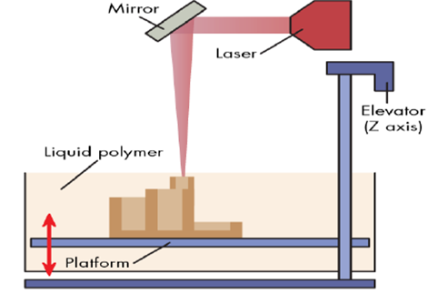
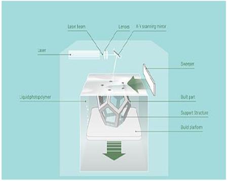
History of Stereo lithography dates back to 1980 and was introduced by Charles Hull. Principle of making solid objects involves successive printing of thin layers of UV curable photopolymer layer by layer. It is used to make implant surgical guides because of high mechanical strength, obturators, surgical stents, and duplication of prosthesis and burn stents. The curing time and the thickness of the layer polymerized are affected by the dynamics involved in the entire procedure. The kinetics can be controlled by the power of the light source, the scanning speed and the chemistry and amount of the monomer and photo initiators. In addition, UV absorbers can be added to the resin to control the depth of Polymerization. The main disadvantage of SLA is the scarcity of biocompatible resins with proper SLA processing properties. Additional challenges are the use of photo initiators and radicals which may be cytotoxic (with long processing times), entrapment of unreacted monomer and residual photo initiator, and inability to create compositional gradients along horizontal planes [1, 3, 4] (Figure 1).
Fused Deposition Modelling
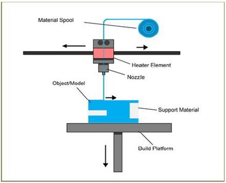
Fused Deposition Modelling developed by Schott Crump. A thermoplastic filament material is extruded through a nozzle controlled by temperature and the material hardens immediately (within .1 sec) after extrusion. The motion of the nozzle head is controlled by a processor and traces and deposits the material in extremely thin layer on to a subsidiary platform. Materials such as acrylonitrile butyrostyrene ABS, polycarbonates and polysulfones are used. Building complex geometries usually necessitates the usage of a second extruder – for example, might extrude a water soluble support material [5]. Accuracy will depend upon the speed of travel of the extruder, as well as the flow of material and the size of each ‘step’. This is the process that is used by most low cost ‘home’ 3D printers. It allows for the printing of crude anatomical models without too much complexity, for example, printing an edentulous mandible [6, 7] (Figure 2).
Selective Laser Sintering
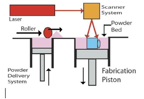
This technology has been brought into usage since mid- 1980s and was developed by university of Texas. A fine material powder is fused by scanning laser, to build up structures incrementally. As a powder bed drops down, a new fine layer of material is spread uniformly over the surface. A high (60μm) level of resolution may be obtained. No support material is required as the structures that are printed are supported by the surrounding powder [8].
Production of facial prosthesis makes use of polymers scaffolds (poly amide or poly Caprolactone). Selective laser sintering is used in fabrication of anatomical study models, cutting and drilling guides, dental models, and also for engineering/design prototypes [9]. Advantages are ease of autoclavability of the materials used, full mechanical functionality of the printed objects, lower cost materials if used in large volume. Disadvantages are powders are messy with increased inhalation risk, techno logy is expensive, and significant climatic conditions such as compressed air are required [9, 10] (Figure 3).
Photopolymer Jetting
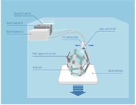
a) This technology uses either a stationary platform and dynamic print head or a stationary print head and dynamic platform. Light sensitive polymer is jetted onto a build platform from an inkjet type print head, and cured layer by layer on an incrementally descending platform. A support structure is laid down in a friable support material. A wide range of resins and waxes for casting, as well as some silicone-like rubber materials can be printed. This technology gives the resolution of apprx.16 microns and gives the easy access for making complex and fine detailed objects [1]. b) They are useful for printing dental or anatomical study models. Implant drill guides may be quickly and cheaply produced with this technology as they are less bulky. 3D Jet printers may have a single print head like a computer printer, or they may have multiple heads to cover the width of the working platform. Either the print head moves across the working platform, or the platform moves back and forth under stationary print head(s). The 3D systems and printers use a UV lamp or a light source to harden the resin or wax after each layer is jetted [1, 6]. Advantages are this technology is fast and cost effective, resolution is high, high-quality finish is possible. Disadvantages are tenacious support material can be difficult to remove completely, support material may cause skin irritation, cannot be heat sterilized, materials cost is high [3, 6] (Figure 4).
Powder Binder Printer
This apparatus uses a modified inkjet head to print. Liquid droplets are made to infiltrate a uniform and sing le layer of powder one after the other. Powder bed drops incrementally and a final model is ready which is built of many layers and a new fine layer of powder is swept over the surface. The un-infiltrated powder supports the model, and so no support material is essential. In order to improve the strength and surface hardness in delicate printed model, a cyanoacrylate or epoxy resin is infiltrated during post processing procedures. Although models are fragile and its accuracy is limited but still models are useful as study models or visual prototypes. This technology proved to be an efficient means of constructing an object in full contour. Models are difficult to sterilize which proves to be a major drawback from a surgical perspective. Advantages are the machines and materials are lower cost, but still less expensive. Lower cost materials and technology, can print in colour, Un-set material provides support, process is relatively fast and materials are safe to use. Low resolution, messy powder, Low strength, difficult to heat sterilize are major disadvantages of this process [1, 2, 3] (Figure 5).
Direct Metal Laser Sintering (DMLS) Process
In the dental office, an impression of a tooth preparation is made to start with, after routine diagnosis and treatment planning. The impression could be a conventional or a digital impression. In the intermediate dental laboratory, the impression is casted and a model is prepared. The model is scanned, and the crown/bridge is designed using CAD design and sent to the central processing unit. The central processing unit is usually a remotely located laboratory with the laser sintering equipment. Special CAM software is used to import a CAD file, usually supplied in the STL format from a scanner /CAD software. CAM software further slices the parts into discrete horizontal layers. Once there are sufficient numbers of crown copings and bridge framework (usually 90–120 units) for a job lot, laser starts production layer by layer in a period of only a few hours. Metal powder is spread across the working platform. A high powered laser beam is used to melt a bed of metal alloy powder by following a predetermined path layer by layer. This path is created by a CAD file. The machine produces several hundred dental prostheses out of metal powder. The speed is approximately 3 min/crown. The DMLS process is performed by two different methods, powder deposition and powder bed method [11]; they differ in the way each layer of powder is applied. The powder bed method is more popular presently, as they offer faster speeds. Inside the build chamber area, there are two platforms, material dispensing platform and build platform (Figure 6).
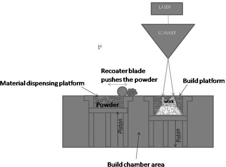
Figure 6: DMLS Machine. The material dispensing platform along with a re- coater blade is used to move new powder over the build platform. The metal powder is fused into a solid part by melting it using the focused laser beam. Parts are built up additively layer by layer, usually 20 μm thick. After a layer is built the build piston lowers the build platform and the next layer of powder is applied. This process allows for highly complex geometries to be created directly from the 3D CAD data, fully automatically without any tools, producing parts with higher accuracy and detailed resolution, good surface quality and excellent mechanical properties. Finally the support material is cut off from the copings/crowns/bridges (Figure 7).
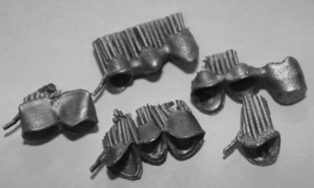
In DLMS there is the concern of metal copings and their bond to veneering ceramic. Tara MA, et al. [12] placed 64 single crowns restorations fabricated using laser sintering method in 39 patients and found that there was no chipping of veneering ceramic during an observation period of 47 months. The failures noted were de-bonding in one case and a case of biologic failure. Authors concluded that the laser sintering process was a promising method of fabrication of porcelain fused to metal crowns [12]. Ten metal ceramic specimens prepared from cast Ni–Cr and Co–Cr alloys exhibited a mixed mode of failure (adhesive and cohesive) whereas five of the laser sintered metal ceramic specimens exhibited mixed failure mode and five specimens exhibited adhesive failure in the porcelain. They concluded that laser sintering was an alternative to conventional casting methods [13].
Conclusion
There is huge impact of 3D imaging and modelling, and CAD technologies on all aspects of dentistry. With the help of digital data it is possible to make accurate, precise and complex geometrical forms in a variety of materials, locally or in industrial centers through 3 dimensional printing. Although everything we make for our patients can be made by a 3D printer, but still single technology is not sufficient to fulfill all the needs of our patient. Recent advances have an ability to produce lower stiff ness scaffolds with high resolution features that allows its application in soft tissue engineering .The technology is gaining importance also in the fields of orthodontics and restorative dentistry with the increase in usage of intraoral scanning systems. Different 3D printing techniques have become imperative in maxillofacial and implant surgery, to assist the complex treatment planning by constructing virtual an atomical models. It is widely acknowledged that surgery may be less invasive and more predictable with the use of surgical guides printed in resins (commonly) or autoclavable nylon. With the evolution of 3D printing it has become possible to replicate desired geometry without an expensive mold and tooling which were not feasible with conventional techniques. 3D printers are becoming accessible and affordable but the cost of running, materials, maintenance, and skill of operators must be taken into consideration. Health and safety protocols must be strictly followed. 3Dprinting takes the efficiencies of digital design to the production stage. The congruence of scanning, visualization, CAD, milling and 3D printing, along with the professions innate curiosity and creativity makes this an exceptionally exciting time to be in dentistry.
References
-
Dawood A, Marti Marti B, Sauret-Jackson V, Darwood A (2015) 3D Printing in Dentistry. Br Dent J 219(11): 521-525.
-
Liu Q, Leu MC, Schmitt SM (2006) Rapid prototyping in dentistry: technology and application. Int J Adv Manuf Technol 29(3-4): 317-335.
-
Helena N Chia, Benjamin Wu M (2015) Recent advances in 3D printing of biomaterials. Journal of Biological Engineering 9: 4.
-
Melchels FP, Feijen J, Grijpma DW (2010) A review on stereolithography and its applications in biomedical engineering. Biomaterials 31(24): 6121-6130.
-
Zein I, Hutmacher DW, Tan KC, Teoh SH (2002) Fused deposition modeling of novel scaffold architectures for tissue engineering applications. Biomaterials 23(4): 1169-1185.
-
van Noort R (2012) The future of dental devices is digital. Dent Mater 28(1): 3-12.
-
Subburaj K, Nair C, Rajesh S, Meshram SM, Ravi B (2007) Rapid development of auricular prosthesis using CAD and rapid prototyping technologies. Int J Oral Maxillofac Surg 36(10): 938-943.
-
Pattanayak DK, Fukuda A, Matsushita T, Takemoto M, Fujibayashi S, et al. (2011) Bioactive Ti metal analogous to human cancellous bone: fabrication by selective laser melting and chemical treatments. Acta Biomater 7(3): 1398-1406.
-
Chen J, Zhang Z, Chen X, Zhang C, Zhang G, et al. (2014) Design and manufacture of customized dental implants by using reverse engineering and selective laser melting technology. J Prosthet Dent 112(5): 1088-1095.
-
Xiong Y, Qian C, Sun J (2012) Fabrication of porous titanium implants by three-dimensional printing and sintering at different temperatures. Dent Mater J 31(5): 815-820.
-
DMLS (2011) http://custompartnet.com/wu/direc- metallaser-sintering
-
Abou Tara M, Eshbach S, Bohlsen F, Kern M (2011) Clinical outcome of metal-ceramic crowns fabricated with laser-sintering technology. Int J Prosthodont 24(1): 46-48.
-
Akova T, Ucar Y, Tukay A, Balkaya MC, Brantley WA (2008) Comparison of the bond strength of laser sintered and cast base metal dental alloys to porcelain. Dent Mater 24(10): 1400-1404.
- Diagnosis and Management of Mental Nerve Paresthesia Secondary to Apical Periodontitis of Mandibular Second Premolar: A CBCT Based Case Report
- A Randomized, Double Blinded Clinical Trial to Compare the Effect of Oral Premedication (Diclofenac Potassium or Dexamethasone) on Post-Operative Pain Following Pulpectomy
- Modified Lip Repositioning Technique for the Management of Excessive Gingival Display
- Integral Role of Non-Dental Providers and Fluoride Dissemination
- Root Canal Treatment Rate in Deciduous Teeth Among 6-Year- Olds in the Era of Discontinuing Water Fluoridation - Historical Cohort Study
- The Impact of the Notch1 on the Migratory Capacity and the Expression of E-Cadherin and CyclinD1 in Ameloblastoma Cells