Characterization of the Iron Ore Deposit Using 2D Resistivity Imaging and Induced Polarization Technique at Diddaye-Potiskum Area, Northeastern Nigeria
2D Electric resistivity imaging and Induced polarization (IP) techniques were used to characterize Iron Ore deposit atDiddaye-Potiskum area of Yobe State, Northeastern Nigeria. The area lies between latitudes 110 46' 00'' and 110 56' 00''N, and longitude 110 00' 00'' and 110 10' 00'' E. The survey was targeted at determining resistivity and chargeabilityvalues that are associated with the iron ore deposit and determining possible depth, thickness of the deposit. Theprotocol chosen were the Wenner-Schlumberger array and dipole-dipole for 2D resistivity and induced polarizationimaging respectively. Data processing and interpretation were done using RES2DINV software. This research hadcharacterized the alluvium deposit in the study area into two: the alluvium deposit that is enriched iron ore and alluviumdeposit with disseminated iron ore. The portion of the models characterized by resistivity and chargeability values of 32Ωm to 886 Ωm and 0.376 m sec to 2.4 m sec respectively is inferred as highly enriched iron ore alluvium; the other part isthe portion of alluvium with disseminated iron ore. The range of resistivity and chargeability values of this portion arerespectively 252 Ωm to 1161 Ωm and 1.28 m sec to 12.11 msec. The study delineated high resistive medium to coarsesandstone with resistivity value that range from 3182 Ωm to 124309 Ωm at fringes of depth range between 9 m to 11 mat models of profile one, four and six. The fracture inferred in this research has been suggested to be filled with theresistive medium to coarse sandstone. This fracture zone cannot be mapped with IP since it is sensitive to disseminatediron ore that the zone probably contains. It can be concluded that the occurrence of iron ore deposit is probably more atnortheast and southwest direction of the survey area that is profile one to six. It can also be inferred that the iron oredeposit is striking in the Northeast-Southwest direction.
Nigeria
Ahmadu Bello University Zaria, Nigeria
Street Potiskum, Yobe state, Nigeria, Tel: 2348067824168; Email:
aliyulawan99@gmail.com deposit is striking in the Northeast-Southwest direction.
Keywords: Iron ore; Chargeability; Electrical Resistivity Imaging; Induced polarization
Introduction
- S/N Deposit Area Estimated Reserves (million tons)
- 1
- Itakpe
- 310
- 2
- Ajabanoko
- 60
- 3 Agbado-okudu
- 60
- 4
- Tajimi
- 20
- 5
- Ochokochoko
- 12
- 6
- Agbaja
- 370.5
Table 1: Some of the notable iron ore deposits in Nigeria
2D electrical resistivity imaging and induced polarization was employed in this research. This was chosen because it is proven successful in identifying iron ore deposit, on the basis of resistivity contrast and chargeability that exist between iron ore deposit and surrounding formation.
Location and Geology of the Study Area
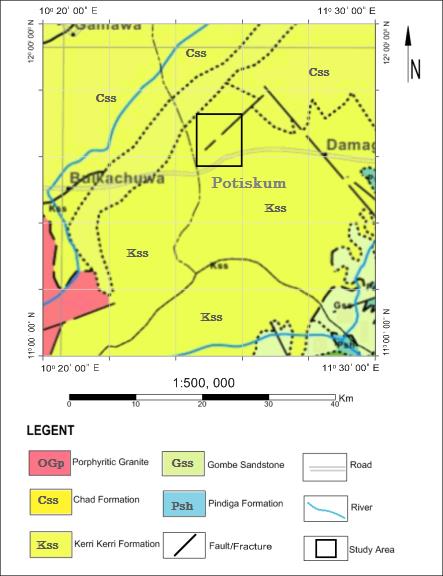
The study area falls within Yobe State in northeastern Nigeria, which is located between latitudes 11046' and 11057'N and longitudes 11000' and 11010'E.The study area is underlain by the sediments of Kerri-Kerri Formation that is predominantly iron rich sandstone and clay with plinth of laterite which is Paleocene in age and has thickness of 130m which is an elevated plain land located in Yobe State, Nigeria [3, 4]. The Kerri-Kerri Formation is bordered in the west by the Crystalline Basement Complex rocks of Bauchi area which are of Precambrian to early Paleozoic age and to the east by the folded Cretaceous rocks of Gombe Sandstone and to the north by the Pleistocene lacustrine clays of Chad Formation [5]. The Kerri-Kerri Formation was laid down on uneven surface of the Basement Complex and folded Cretaceous rocks with the thickness variation from few metres to estimated 300 m [6, 7]. The Kerri-Kerri Formation comprises medium coarse sandstones, sands, sandy gravel and sandy clay, although fine sands, siltstone and clay stones are well developed [5]. The Kerri-Kerri Formation is a continental sequence of Paleocene age deposited in a wide variety of sedimentary environments, namely alluvial, fluvial and marginal lacustrine, although deltaic environment has also been suggested [8, 3]. The Kerri-Kerri Formation outcrops in a number of places particularly in the Alkaleri, Dukku and Potiskum areas respectively. Figure 1 shows the geological map of the study area and it reveals linear feature traversing northeastern direction and is inferred as fault/fractures.
Methodology
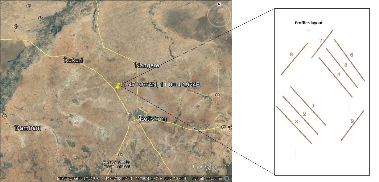
Wenner Schlumberger and Dipole-Dipole were used in 2D resistivity imaging and IP techniques respectively for this research. The field measurement began with laying out the cables and electrodes along the chosen profile while coordinates of the start, middle and end points along the profile are recorded. Each cable has 21 take outs. The terrameter SAS 1000 and the ES 464 were placed at the center of the layout. The two cables were connected to the Electrode selector (ES 464) at the centre of the layout. Take-out 1 and take-out 21 were made to overlap at the cable ends and at the layout centre. The serial port of the Terrameter was connected to the electrode selector and the electrodes connected to all the take-outs at the intervals of 2m on the electrode cables using cable jumpers. Electrodes were drived into ground by hand. However, hammering and wetting were done on dry and hard ground. The terrameter was then connected to an external 12 volts battery and switched on, which automatically switches on the Electrode Selector and the system set-up echoed on the screen. The instrument was set to resistivity mode and LUND Imaging for taking measurement of Wenner-Schlumberger and IP mode for Dipole-Dipole measurement. The programmes automatically continue to measure using the two electrode cables. As measurements continued apparent resistivity/chargeability values are echoed on the screen. When measurements on each layout were finished, the programme was stopped and the Terrameter switched off. The instruments were then transferred to a new profile and the entire process repeated until all the profiles were completed. While acquiring data along the profiles, the positions of reference points along the lines were noted. In all the measurements made along nine profiles (Figure 2).
Results
The electrical resistivity images and Induced polarization of the earth’s subsurface along the profiles obtained in the study area are presented in Figures below. Nine profiles were taken from the study area for this work. Six of the profiles (profile 1, 2, 3, 4, 5, 6,) were taken along north-east to south-west direction of the survey area while the remaining three were taken at adjacent directions. The inversion result for each profile is shown depicting the images of the geoelectric sections obtained from the processed data. The results shows two images for each profile. The upper image is a plot of resistivity model obtained after definite number of iterations of the inversion programme. The lower image shows chargeability model of induced polarization obtained after iteration of the inversion programme.
Profile One
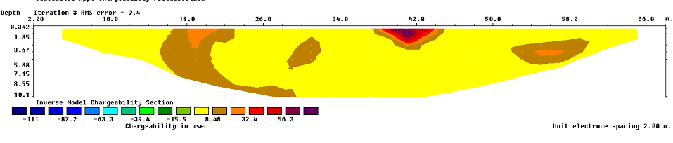
Figure 3 shows the resistivity model and chargeability model of profile one. The resistivity model reveals an area as alluvium deposit of resistivity value that ranging from 62 Ωm to 763 Ωm with distinct patches of coarse sandstone with high resistivity values that ranges from 2674 Ωm to 11490 Ωm. The coarse sandstone with near oval shape falls between 38 m and 44 m along the profile and it extends from 0.5 m to 7.9 m below the surface. The chargeability model of the profile shows low chargeability value of 1.24 msec at depth of 4.0 m and 9.2 m between the distance of 2 m to 6 m and 20 m to 30 m respectively. So also at a distance 38 m to 42 m and distance of 50 m to 62 m there are occurrences of low chargeability of 1.24 msec which correspond to chargeability of iron ore deposit. The rest of the areas of the profile have chargeability ranging from 6.18 msec to 16.10 msec which are likely to be sandstone.
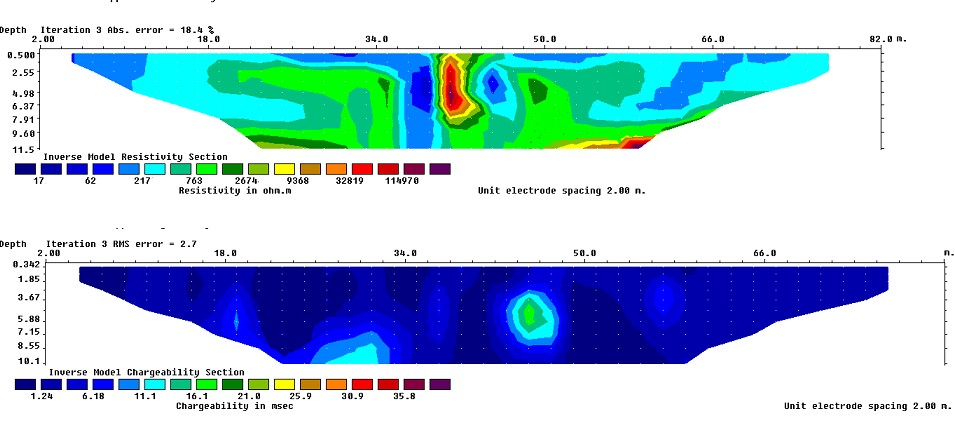
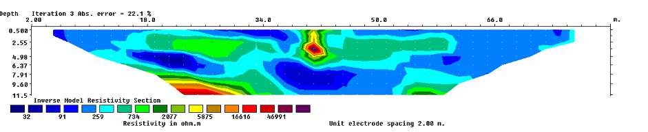
Figure 4 shows resistivity model and chargeability model of profile two. The resistivity model reveals alluvium deposit with a resistivity values ranging from 103 Ωm to 1015 Ωm and it has thickness of 9.3 m. There is appearance of high resistive medium to coarse sandstone at the fringe with resistivity value of 3182 Ωm at a depth of 9.6 m to 11.5 m. At distance 38 m to 44 m there is occurrence of nearly oval shape with high resistive coarse sandstone with resistivity value ranging from 9978 Ωm to
31281 Ωm. The chargeability model shows a thin top soil with a value of -0.498 msec and underlying it is 2.480 msec chargeable layer of depth ranging from 1.85 m to 10.10 m. At distance of 24 m to 33 m and depth of 7.15 m to 10.10 m there appears the occurrence of sandstone with chargeability ranging from 6.46msec to 14.40 msec. The chargeable zones with 2.4 msec and resistivity value ranging from 103 Ωm to 1015 Ωm in the profile are likely to contain iron ore.
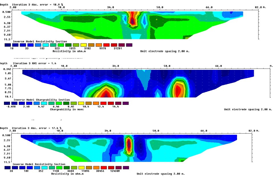
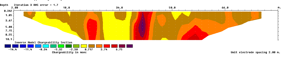
Figure 5 shows resistivity and chargeability models of profile three. Resistivity model reveals that the profile comprises alluvium deposit which has resistivity value ranging from 109 Ωm to 1138 Ωm. The top soil layer at depth of 2.55 m has a resistivity value of 109 Ωm, and it has thickness 1.8 m. Underlying the top soil is a thin layer of thickness 3 m that extended to a distance of 18 m with resistivity of 352 Ωm. At a distance of 20 m, the thickness of the layer increases to 9.05 m. At a horizontal distance 38 m to 44 m there appears the occurrence of very high resistivity (11896 Ωm to 124309 Ωm) that extended to a depth of 7.91 m. The chargeability model reveals that between the horizontal distances of 12 m to 18 m, 24 m to 30 m, 31 m to 39 m, and 66 m to 70 m, low chargeable zone of 1.16 msec exists, while the rest of the profile has chargeability values ranging between 3.0 msec to 15.4 msec. The areas with chargeability 1.16 msec are likely to be iron ore deposits, whereas areas with chargeability ranging from 3.0 msec to 15.4 msec are likely to be sandstone.
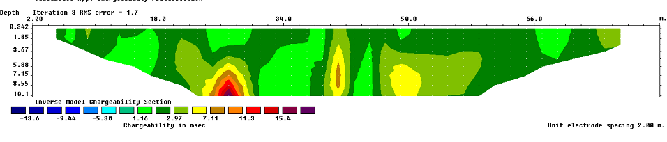
Figure 6 shows resistivity and chargeability models of profile four. Resistivity model reveals that the profile is of alluvium deposit with resistivity values ranging from 32 Ω m to 734 Ωm and depth of 7.91 m. There is occurrence of high resistive coarse grain sandstone with resistivity values ranging from 2077 Ωm to 46991 Ωm, at depth ranging from 7.91 m to 11.50 m. At a distance of 39 m to
44 m, coarse sandstone appears. Chargeability model reveals that the profile is covered with low chargeability value of 0.717 except at horizontal distances of 24 m to 29 m and 38 m to 45 m, chargeability of 3.74 msec to 6.75 msec occurred. Also at a distance of 50 m, there is appearance of low chargeability values (3.74 msec to 5.67 msec).
Profile Five
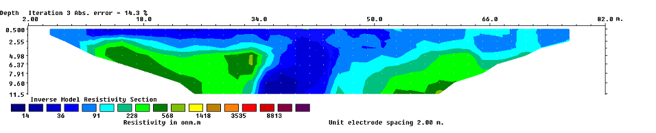
Figure 7 shows Resistivity model and Chargeability model of profile five. Resistivity model reveals a top soil layer that has resistivity value of 111 Ωm and depth of 1.8 m. Underlying the top soil is alluvium deposit with high resistivity ranging from 313 Ωm to 886 Ωm and it has thickness of 8.3 m. At distance between 38 m to 44 m, there is occurrence of high resistive medium to coarse sandstone (2504 Ωm) with a depth of 7.91 m. Chargeability model reveals the occurrence of low chargeability value of 1.28 msec between horizontal distances of 5 m to 10 m, 22 m to 33 m, 35 m to 37 m and 50 m to 57 m with depth ranging from 1.85 m to 4.50 m, 1.83 m to 10.00 m, 1.5 m to 10.1 m, 0.5 m to 10.1 m respectively. These are suspected to be iron ore deposit.
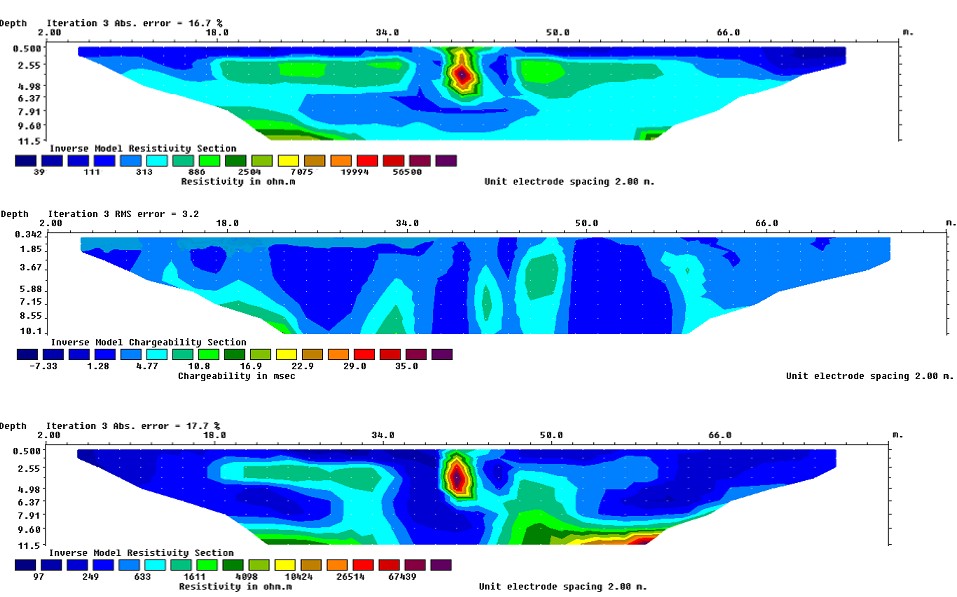
Profile Six
Figure 8 shows Resistivity model and Chargeability model of profile six. Resistivity model reveals that the profile comprises alluvium that has thickness of 9.8 m. There is occurrence of patches of medium to coarse sandstone with resistivity ranging from 1611 Ωm to 4098 Ωm at distance between 46 m to 50 m. At fringe of the profile, high resistive coarse grain sandstone with resistivity value of 26514 Ωm to 67439 Ωm had occurred.
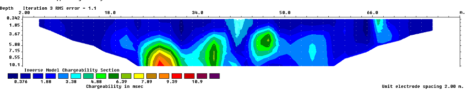
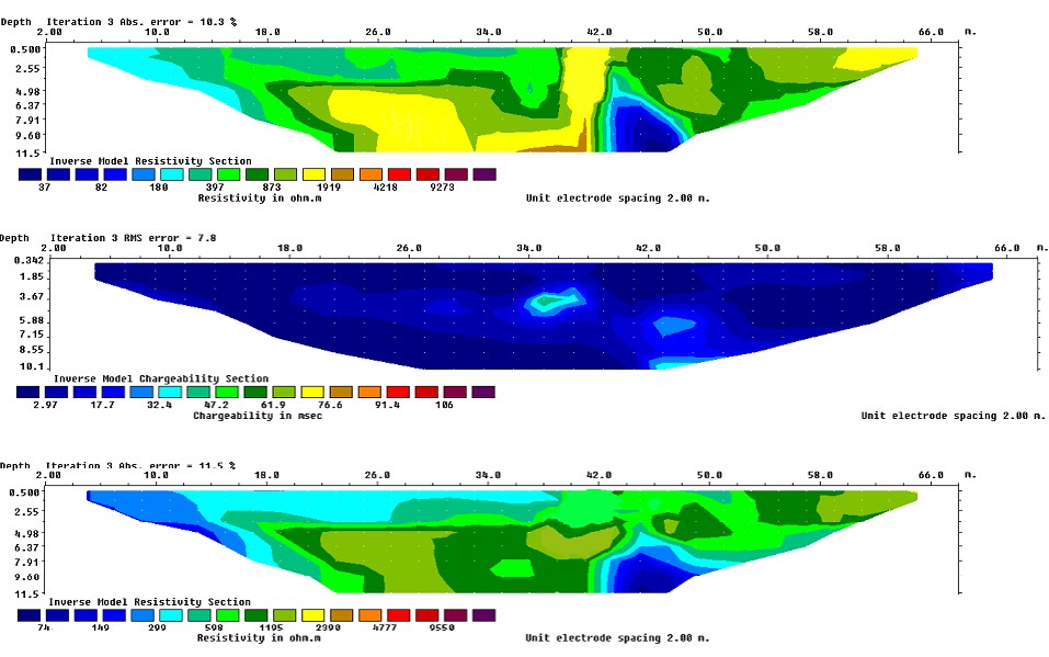
Figure 9 shows Resistivity model and Chargeability model of profile seven. Resistivity model reveals that the profile comprises alluvium deposit with resistivity values ranging from 14 Ωm to 568 Ωm. At a distance of 10 m to 52 m and depth of 2.5 m, the resistivity values is ranging from 36 Ωm to 91 Ωm with depth of 4.98 m and it is inferred as alluvium with disseminated iron ore. At
Profile Eight
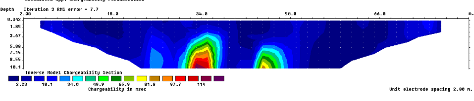
Figure 10 shows the resistivity model and chargeability model of profile eight. Resistivity model reveals that the profile is alluvium with disseminated iron ore that has resistivity value ranging from 37 Ωm to 1919 Ωm. Chargeability model shows the profile has chargeability value of 2.97 msec to 17.70 msec. At middle of the profile around 34 m to 38 m and depth between 3.5 m to 4.5 m there is occurrence of siltstone with chargeability value ranging from 47.2 msec to 61.9 msec. The profile is dominantly of alluvium with disseminated iron ore.
Profile Nine
Figure 11 show resistivity model and chargeability model of profile nine. Resistivity model reveal that the profile is made up of alluvium deposit that has resistivity value ranging between 74 Ωm to 1192 Ωm. At a distance of 2 m to 38 m is a layer that has resistivity value of 299 Ωm. The average depth of the profile is 11.5 m. There is
Discussion
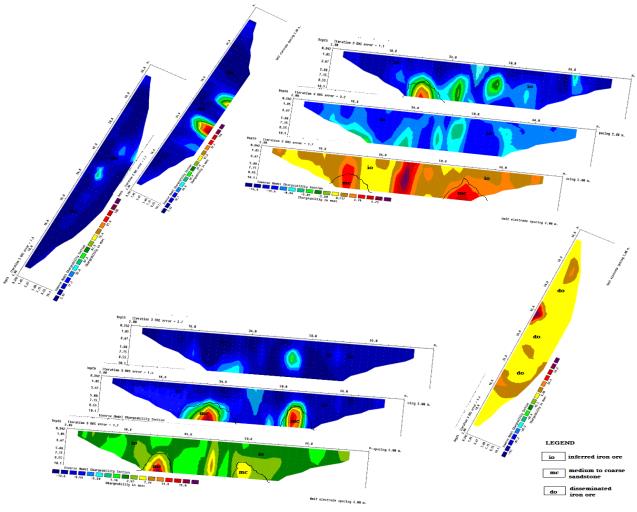
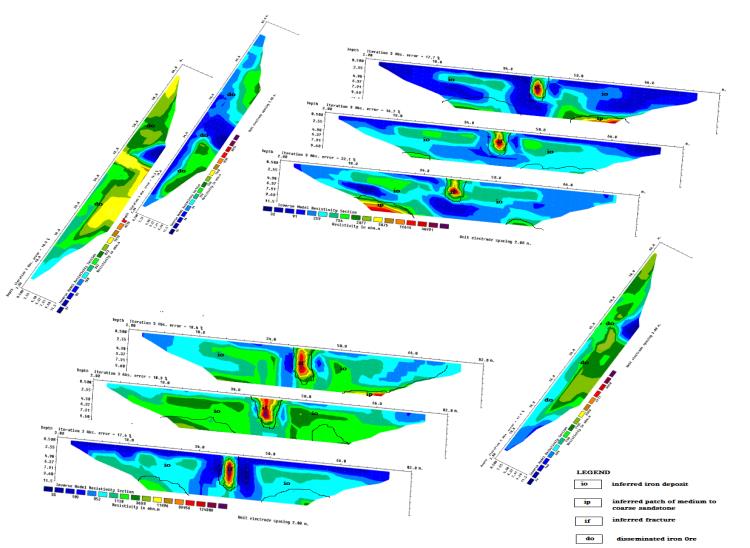
Figure 12 and 13 respectively show, in one view the spatial display of resistivity and chargeability models of all the profiles. The maximum depth displayed by the figures is 12 m and nearest borehole log (Figure 13) and previous studies were used as control, the depth suggest that the investigation is limited to alluvium deposit in the stratigraphic sequence of the chad basin in which the study area lies (Figures 12 & 13).
The resistivity and chargeability values of the subsurface lies between 14 Ωm to 124309 Ωm and 0.376 msec to 15.000 msec respectively and it reflect variations in subsurface materials. The portion of the models respectively characterized by resistivity and chargeability values of 14 Ωm to 1611 Ωm and 0.376 msec to 12.400 msec at an average depth of 0.5 m is inferred as iron rich alluvium. This inference was made with surface geology and standard resistivity and chargeability values of rocks and minerals used as control and on the basis that iron rich layer is characterized by low resistivity and chargeability values.
Profile one and four were acquired close to exposed iron ore deposit and they show that the portion of the iron rich deposit is characterized by resistivity and chargeability values of 32 Ωm to 886 Ωm and 0.376 msec to 2.4 msec respectively. The study characterizes the portion of iron rich alluvium into alluvium that is highly enriched with iron ore and alluvium with disseminated iron ore. Thus the portion of the iron rich alluvium that are respectively characterized by low resistivity and chargeability of 32 Ωm to 886 Ωm and 0.376 msec to 2.400 msec are inferred as alluvium that is highly enrich with iron ore, while the portion that are respectively characterized by resistivity and chargeability values of 252 Ωm to 1611 Ωm and 1.24 msec to 12.40 msec are inferred as alluvium with disseminated iron ore. The thickness of alluvium highly enriched with iron ore ranges from 3 m to value that extends beyond the probe limit of the electrode spacing of the survey which is 11.5 m.
Models of the profile eight and nine that are taking 50 m northwest and southeast away from the exposed iron ore deposit, this suggested that the area is dominantly alluvium with disseminated iron ore except the fringes at depth ranges between 7.1 m to 11.0 m at between 32 m to 50 m along the profile.
Conclusion
Electrical resistivity imaging and induced polarization, carried out at Diddaye-Potiskum area, Northeastern Nigeria, have successfully addressed the aim of the investigation. The study characterized the iron rich alluvium into two, thus; the portion of alluvium that is highly enriched iron ore with resistivity and chargeability values of 32 Ωm to 886 Ωm and 0.376 msec to 2.4 msec respectively. This portion occurred at an average depth of 0.5 m and the thickness ranges from 3 m to depth beyond the probe limit of the electrode spacing of the equipment used for this investigation. The other is the portion of alluvium with disseminated iron ore. The range of resistivity and chargeability values of this portion are respectively 252 Ωm to 1161 Ωm and 1.28 msec to 12.11 msec. The maximum depth of this portion is 11.5 m but the thickness could not be provided because of the probe limit of the electrode spacing of the equipment used for investigation.
The study delineate high resistive medium to coarse sandstone with resistivity value that ranging from 3182 Ωm to 124309 Ωm at fringes of profile one, four and six. The inferred fracture in this investigation has also been suggested to be filled with the high resistive medium to coarse sandstone. The study also demonstrated that resistivity tomography can be used to map subsurface fractures even with the difficulty of identifying structural feature in a loosely consolidated nature of the sediment (like in this study area) and extensive lateritic cover in Kerri-Kerri formation [10].
The top of the zone is between 0.5 m to 2.5 m while depth of the bottom lies between 6.4 m to 9.6 m. This zone appears to extend beyond the spatial limit of the measurement, thus implying that the structure may be continuous across the basin. This shows that the fractured zone is a near surface fracture, as it probably corresponds with the structural trend that is known in the basement complex and cretaceous cover.
This research shown that the inferred fracture zone filled with medium to coarse sandstone cannot be mapped with IP data acquired with dipole-dipole array since IP is sensitive to disseminated minerals.
References
-
Annual Report (2009) Reserves, Resources and Availability of Energy Resources. BGR (Bundesanstalt fur Geowissenschaften und Rohstoffe), Federal Institute for Geosciences and Natural Resources.
-
NMS (2007) Overview of the Nigerian Mining Sector. Annual conference of Nigerian Mining and Geosciences Society.
-
Carter JD, Barber W, Tait EA (1963) The Geology of parts of Adamawa, Bauchi and Bornu provinces in north eastern Nigeria. Geological Survey of Nigeria. Bulletin (30): 108.
-
Avbovbo AA, Ayoola EO, Osahon GA (1986) Depositional and structural styles in Chad basin of northeastern Nigeria. Am Assoc Pet Geol Bull 70 (12): 1787-1798.
-
Dike EFC, Dan Hassan MA (1992) The Geology and Aquifer Properties of the Tertiary Kerri-Kerri Formation. Journal of Nigerian Association of hydrogeologists 3: 20-30.
-
Dessauvagie TFJ (1975) Explanatory Note to the 1:1,000,000 Geological Map of Nigeria. Journal of Mining and Geology, Nigeria.
-
Adegoke OS, Janduchene RE, Agumanu AE, Ajayi PO (1978) Palynology and age of the Kerri- Kerri Formation, Nigeria. Revista Espanola Micropaleontology 10: 267-283.
-
Du Preez JW, Barber DFM (1965) The Distribution and Chemical Quality of Groundwater in Northern Nigeria. Bull Geological Survey _Nigeria._
-
NGSA (2004) Fully conscious of the fact that Geological Maps are planning tools for the economic development of any nation. Edition of Geological Map of Nigeria and other maps.
-
Benkheil J (1986) Structural map of the Upper Benue Valley. Journal of Minning and Geology.
-
(2010) ABEM Instrument AB, Terrameter SAS1000/4000 LUND Imaging System Instruction Manual.
- Sense, Gravity, Parity & Chirality in Mathematical Physics
- Quantum Lattice Simulations PHYSICS: Microcircuit Particle Formation and Observable Macroscopic Irreversible Time - A Discrete Lagrangian with Cellular Automata Framework
- Quantum Biology from Biomacromolecule to Cell, and Central Dogma Described by Quantum Theory
- Focus, Agility, Speed and Technology (FAST) for Sustainability and Growth
- Square Root Metric Geometry and Pati-Salam Model in Curved Space-Time
- A Simple System Demonstrating the Mpemba Effect in Classical Mechanics