Comparison of Constant and Adjustable Drawbar for a Domestic Horticulture Tractor
In this study, adoption study of drawbar pull from constant height to adjustable height was investigated for improving mechanical structure, increasing efficiency of fuel consumption, decreasing slippage of domestic horticulture tractors. Materials were a horticulture tractor, an orchard sprayer, speed measurement sensor, load cell and fuel consumption. New drawbar which connection height of implements can be adjustable was designed and manufactured for horticulture tractor. Constant height drawbar and adjustable height drawbar were compared for pulling force, forward speed and fuel consumption by using orchard sprayer. Tests were carried out for 2 km, 1 hour, 3rd gear at 2500 rpm of engine. Forward speed was determined as 15 km/h for drawbar pull test and fuel consumption tests. According to the fuel consumption results; the adjustable drawbar was better than constant drawbar 0.29 l/h on soil and 0.34 l/h on concrete surface. Forward speed with adjustable drawbar was faster than constant drawbar as 1.7 km/h for field and 2.0 km/h for concrete surface. Drawbar pull of the adjustable drawbar was less than constant drawbar 36.58 N on concrete road and 74.29 N in soil surface even there wasn’t any problem for pulling sprayer. Work was performed with less drawbar pull and less fuel consumption. Adjustable drawbar suggested to manufacturer for investigated horticultural tractor because of its advantages due to constant drawbar.
Introduction
Trailed equipment is connected to the tractor via drawbar. Machines such as trailers that are drawn by the tractor are connected to the tractor using a drawbar that can rotate around its own axis. In some cases, drawbar is used which is a lama with holes that is connected to the lower arms of the three point linkage system [1].
Horticulture tractors are the smallest tractors that are used in vegetable gardens that cultivate vegetables for the market, nursery gardens, small gardens, chicken farms etc. as well as many other small agricultural establishments. The location of the drawbar affects tractor control as well as its ability to draw along with the ability of trailers to follow the trail. Only the drawbar should be able to rotate around the longitudinal axis of the tractor and the hole of the trailer beam should remain constant. Thus, the trailer and the tractor can turn against each other. This ability to turn prevents the tractor from additional strain when the dumper trailer topples over. The height of the drawbar grasp from the ground should be the same with that of the drawbar beam. If the drawbar is lower, the load of the rear wheels of the tractor decreases whereas the load on the front wheels increases. This makes it more difficult for the tractor to apply the required draft. Many problems arise such as accidents with severe injuries (trailer cut-off etc.), loss of draft and control difficulties. It is important to pass from the fixed rear traction system to the adjustable height rear traction system for horticulture tractors. In this study, the transformation from fixed drawbar to adjustable height drawing has been carried out for a locally manufactured horticulture tractor. The objective of the study was to enhance the mechanical structure of locally manufactured tractors, to increase efficiency in fuel consumption while decreasing loss of speed. In addition, it is also thought that this study will also eliminate the additional workload resulting from the connection of the trailer to the tractor thereby eliminating the additional loss of time.
Materials and Methods
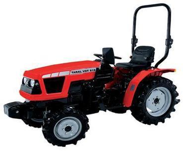
A horticulture tractor, pulverisator, speedometer, load cell and fuel meter were used in the study as material. Tractor: Taral VST 818 horticulture tractor was used in the study (Figure 1). Technical properties have been given in Table 1 [2].
| Model | Taral VST 818 | ||||
| Max. power (ISO) HP | 18.0@2700 (DIN 70020) | ||||
| Max. Engine speed(min-1) | 2900 | ||||
| Number of the cylinder | 3 | ||||
| Number of the gear | 6 forward, 2 back gears | ||||
| Hydraulic system capacity( kg) | 700 |
Table 1: Technical specifications of Taral VST 818 tractor ((http://taral.com/). Tractor drawn tools and equipment are usually co
| Model | TP 1200 milenyum | ||||
|---|---|---|---|---|---|
| Depot capacity (litre) | 1200 | ||||
| Material | Polyester | ||||
| Pump type | Tar 125 | ||||
| Flow rate (l/min) | 125 | ||||
| Speed (min-1) | 540 | ||||
| Pressure (kg/cm2) | 0-50 |
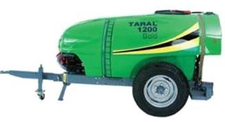
Table 3: Taral 1200 orchard pulverisator technical specifications Fuel Meter: Aqua Metro Contoil VZD 4 brand flow meter with a di
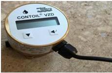
| Measurement step | 0.01 l | ||||
|---|---|---|---|---|---|
| Measurement interval | 1 – 135 l/h | ||||
| Connection | M14 x 1.5 |
Table 2: Aquametro Contoil Vzd Fuel meter technical specifications [3] Load Meter: ESİT SC load cell with the technical propertie
| Max. capacity (emax) | Kg | 10000 | ||||||
|---|---|---|---|---|---|---|---|---|
| Total error | % | <=+-0.05<=+-0.02<=+- 0.015 | ||||||
| Min. load | %Emax | 0 | ||||||
| Overload capacity | %Emax | 150 | ||||||
| Breaking capacity | %Emax | 300 |
Table 5: Magnetic sensor technical specifications Interface: Spider 8 HBM brand interface was used in the study to analyze and re
- Indicator: Baykon Bx1 T the technical properties of which have been given in Table 5 was used in order to read the load values in the load cell [6].
- Linearity &Temperature coefficient
- % 0.0015 FS ; ≥ 2 ppm/°C
- Measurement speed
- Max. 100 measurement/s
- Energy requirement
- 5 VDC, max. 100 mA
- Data output
- Standard RS 232C
Table 4: Baykon Bx1 T Indicator Technical Specifications.
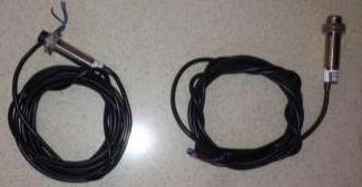
battery was transformed into 220 V current via the inverter and was used in the study. Speedometer: MEFA magnetic detector the technical properties of which have been given in Table 6 was used in the study (Figure 6).
| Current | 10-60 Volt DC | ||||
|---|---|---|---|---|---|
| Radius | M12x1 metal | ||||
| Length | 50 mm | ||||
| Output | NPN | ||||
| Sensing distances | 4mm | ||||
| Connection type | 2m, 3 cable |
Table 6: Magnetic sensor technical specifications Interface: Spider 8 HBM brand interface was used in the study to analyze and re
| Connections | RS-232 Kablo | ||||
|---|---|---|---|---|---|
| Software | Catman professional | ||||
| Frequency | 50 – 60 Hertz |
Table 7: Spider 8 HBM Interface Technical Specifications.
Design and Production of the Adjustable Traction System
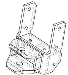
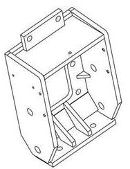
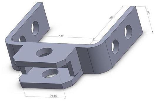
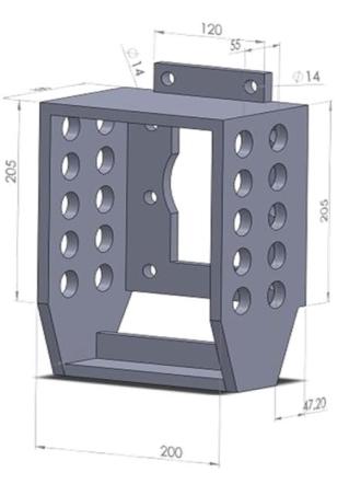
Dimensioning of the bearing elements of the adjustable traction system was made in accordance with the dimensions allowed by the space around the tail shaft of the tractor. The technical drawings and dimensions of the adjustable traction system have been shown in Figure 7. The diameter of the lift holes on the cover was 18.5 cm, with 5 cm intervals in the vertical axis and 5.5 cm between two holes in the horizontal axis (Figure 7)
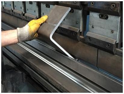
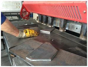
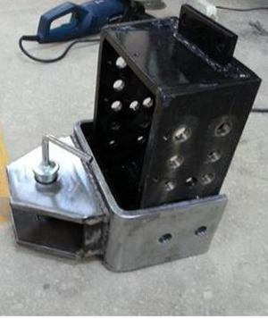
The technical drawings of the adjustable drawbar along with the manufactured product as a result of the works carried out in the workshop have been given in Figure 9.
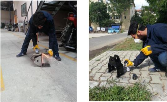
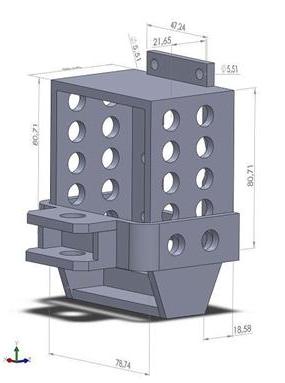
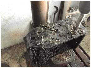
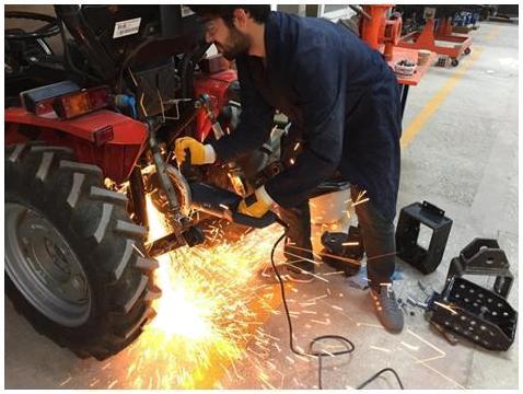
Figure 9: Adjustable drawbar. Grinding and sanding operations were carried out in order to cleanse the adjustable traction system from any possible roughness, coating was carried out afterwards to prevent rusting in the system and to provide an aesthetically pleasing appearance. The completed adjustable traction system ready for use was then mounted on the tractor to carry out the trials (Figure 10).
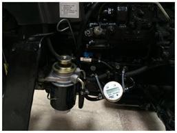
Measuring Fuel Consumption
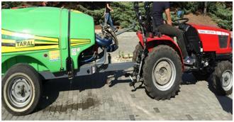
Pulverisator used with the horticulture tractor was connected to the fixed position drawbar on the tractor and the produced adjustable traction system after which fuel consumptions were determined and compared for a distance of 2000 m, 1 h work time and 2500 r/m operating speed. The trials were carried out at fixed speed, fixed revolution and fixed working time in road and terrain conditions for fixed and adjustable drawbar (Figure 11).
Draft Measurement
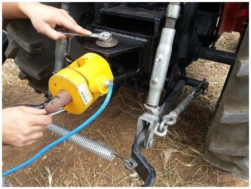
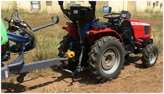
Draft was tested during the trials for fixed drawbar and adjustable traction system on the soil and concrete surface; data were measured via the load cell connected between the drawbar and the pulverisator. Data were read from Baykon Bx1 T indicator (Figure 12).
Speed Measurement
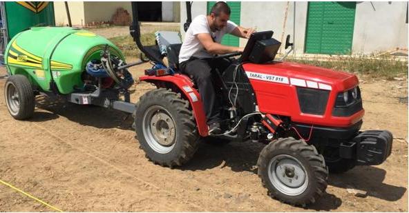
The trials were carried out for the fixed drawbar and height adjustable traction system for the road position at 3rd gear, 2500 r/m for the Figure to which pulverizator connected to the fixed drawbar is connected. Results for the concrete surface and the field conditions were compared (Figure 13).
Results and Discussion
Fuel consumption tests were carried out at 2500 rev/min for 15 km/h fixed speed for a period of 1 hour. Fuel consumption values obtained during the tests for a length of 15.000 meters have been shown in Table 8. Fuel consumptions were measured as 2.41 l/h for field conditions and as 2.23 l/h for concrete surface with fixed drawbar. Whereas the values were 2.12 l/h and 1.89 litres for field and concrete surface conditions respectively with adjustable traction system.
| Exist drawbar (l/h) | |||||||||
|---|---|---|---|---|---|---|---|---|---|
| Adjustabl (l/h) | e | D | ifference | s D | ifference | s | |||
| (l/h) | (%) | ||||||||
| Concrete surface | 2.23 | 1.89 | 0.34 | 15 | |||||
| Soil surface | 2.41 | 2.12 | 0.29 | 12 | |||||
| Differences | 0.18 | 0.23 |
Table 8: Fuel consumption Speed measurement tests were carried out in 3rd gear for 1 hour at 2500 r/m under road conditions. The
Table 8: Fuel consumption Speed measurement tests were carried out in 3rd gear for 1 hour at 2500 r/m under road conditions. The values obtained with fixed drawbar were 13 km/h at field conditions and 14 km/h on concrete surface, whereas the values obtained with the adjustable traction system were 14.7 km/h under field conditions and 16 km/h on concrete surface (Table 9).
| Exist drawbar (km/h) | ||||||||
|---|---|---|---|---|---|---|---|---|
| Adjustabl (km/h) | e | D | ifferences (km/h) | Difference | s | |||
| (%) | ||||||||
| Concrete surface | 14 | 16 | 2 | 14 | ||||
| Soil surface | 13 | 14.7 | 1.7 | 13 | ||||
| Differences | 1 | 1.3 |
Table 9: Forward speed (km/h) Draft measurement results were obtained with 3 repetitions during trials carried out with Taral hor
Table 9: Forward speed (km/h) Draft measurement results were obtained with 3 repetitions during trials carried out with Taral horticulture a for the fixed and adjustable traction system. When the average results were examined for fixed traction the minimum value in field conditions was 187.23 N, whereas the maximum value was 1328.0 N; for the concrete surface the minimum value obtained was 168.09 N whereas the maximum value obtained was 1219.58 N. When the average results for the adjustable traction system were examined, it was observed that the minimum value obtained under field conditions was 172.0 N, whereas the maximum value was 1253.71 N; the minimum value obtained for the concrete surface was 161.20 N, whereas the maximum value was 1183.0 N (Table 10).
| d | Exist rawbar (N) | |||||||
|---|---|---|---|---|---|---|---|---|
| Adjustabl (N) | e | D | ifferences (N) | Difference (%) | s | |||
| Concrete surface | 1219.58 | 1183 | 36.58 | 3 | ||||
| Soil surface | 1328 | 1253.71 | 74.29 | 5 | ||||
| Differences |
Table 10: Pulling force.
Conclusions
Problems and disadvantages related with fixed traction for the Taral 818 horticulture tractor were determined as a result of the trials and calculations carried out. Design and prototype production for the adjustable traction system was carried out. Tractor travel speed, traction force, hourly fuel consumption values were measured to compare the developed adjustable traction system and the fixed drawbar. When the fuel consumption values were examined, it was observed that 0.29 l/h and 0.34 l/h less amount of fuel was consumed with the designed adjustable traction system in comparison with the fixed traction system under field and road conditions respectively. When the speed measurement results were examined, it was observed that the designed adjustable traction system can go 1.7 km/h and 2.0 km/h faster in comparison with the fixed traction system under the same in field and road conditions respectively with the same load. When the draft results were examined, it was observed that the maximum values for the adjustable traction system were lower by 36.58 N on concrete surface and by 74.29 N under field conditions in comparison with fixed traction and thus it was determined that the newly designed adjustable traction system decreases the load on the tractor. It has been put forth that the adjustable traction system adjusts the most suitable position for drawbar thus resulting in lower traction force and lower fuel consumption and therefore it is suggested to use it in all locally manufactured horticulture tractors.
Acknowledgements
Authors would like to thanks to TUBİTAK and TARAL to support “Study converting from constant drawbar to adjustable drawbar for Taral Orchard Tractor- Taralbahçetraktöründesabitarkaçekidenyükseklikayarlıar kaçekiyegecişçalışması”.
References
-
Sabancı A (1999) Ergonomics (in Turkish: Ergonomi). Cukurova University Faculty of Agriculture, Department of Agricultural Machinery Department, Lecture Book, Adana, Turkey.
-
Taral (2016) Compact tractors (in Turkish: Kompakttraktörler), (Erişimtarihi: 18/06/2016).
-
Aquametro (2016) Aquametro, id=21927 (ErişimTarihi: 22/05/2016).
-
Sabancı A (1997) Agricultural Tractors (in Turkish: TarımTraktörleri), Cukurova University Faculty of Agriculture Course Books General Publication No: 46, Adana, Turkey Pp: 113-167.
-
Esit (2016) Products (Indicators and Control Devices), (Access date: 12/05/2016).
-
Baykon (2016) Products, (Access date: 03/06/2016).
-
HBM (2016) Specialized Data Acquisition, (Erişim tarih: 28/05/2016).
- Enhancement of Vegetative Growth and Fruit Yield in Cucumber (Cucumis sativus L.) via Spiritual Blessing (Biofield) Energy Intervention
- Production of Açaí (Euterpe oleracea Mart.) under Different Agroforestry System Management Intensities in Amazonian Floodplain (Varzea) Forests
- Coffee and the Production Region: What is the Secret to the Expression "Quality"?
- Experiential Agripreneurship Training in Sub-Saharan Africa: Integrating a Business Incubator into Postgraduate Livestock Education at the University of Buea
- Advances in Agricultural High-Quality Development
- Linking Compost Residue to ABAGE in Plants - a Short Note