G-Reactor at Micro-Plant
The stirrer reactor govern the industrial pharmaceutical productions up to the present, however the complex transmission systems may increase the costs exponentially with the power rates and the hermetic rector sealing. G-reactor improves the analogous reactors with simple pneumatic power device to heavy duty performances at high technological risks by pathogens and per substitution of complex transmissions by own-design; a single compression unit produces the sterile air to the power input of micro-plants and the oxygen of aerobic processes; important economic technical profits is foreseen; microplants distinguishes by small installations for compressed air and the services with overall automatic control available; the reliable performance for the human health, variable speed and standard impeller system, simple sterilization, safe sampling and supplies, foam-breaks to avoiding chemicals and simple automatic flow control distinguish the installations. The mathematical simulation of G-reactor performances to the mixing operations at gas-liquid systems to mass-transfer is shown; a solved example to a specific process illustrates the calculus fundamentals; the software enables the calculus of consumption parameters to the reactor scale-up and micro-plants of maximum capacity; the descriptive data analysis is discussed for the primary technical evaluations and general conclusions. The innovation is proposed for the small production scale of drugs and the unit operations of the chemical industry; a brief technical description of micro-plants and the production of sterile air may lead to the process engineering and the preliminary analysis of costs. The prophylactic treatment of the residual gas flow is shown.
Introduction
Gas-liquid systems are present to a number of industrial processes, a common application involves the mass-transfer of a sparingly soluble gas into a liquid where a reaction may occur, for example the fermentation under aerobic conditions to the production of antibiotics, steroids and single-cell proteins; [1] other productions such as vaccines and biological drugs is accomplished in stirrer reactors and batch processes up to the present.
Complex transmission systems of stirrer reactors may increase the costs and the investment considerably; regarding the reactor volume and the power input, common driving mechanisms are integrated by the induction electric motor, bearing housing, gears box, magnetic transmission and the aseptic mechanical seal indistinctly to warrant the hermetic operation. G-reactor improves the analogous stirrer reactors with simple pneumatic device to high technological risks of biochemical processes with no system failures and extraordinary maintenances by own-design and per substitution of the variable speed induction electric motor, the magnetic transmission and the aseptic mechanical seal indistinctly of commercial reactors.
New reactor designs should be capable of reliable operation and control enough to enabling the overall plant optimization over a reasonable range of process fluctuations; at this goal this innovation is proposed; other considerations concerning the reactor productivity and yield, product purification, water management, energy requirement and wastes must be handled on design time [2].
Previous jobs develops the software and the calculus fundamentals to the know-how on design and construction of this innovation from the scratch up to G-reactor at micro- plant on this era of bacteria and diseases where new drugs and researches is necessary. In agreement with the compressive technical knowledge supporting this job and the importance at present, the author encourage the reactor construction and the practical essays; this job may contribute to the creation of new research works and developments and to references at pre-grade to the design and construction of chemical reactors.
G-Reactor: Key Results
G-reactor distinguishes by simple pneumatic power device to warrant the reliable operation to high technological risks of biochemical processes to the human health and extraordinary maintenances by own-design; the low cost of manufacture and the investment to powered micro-plants by a single compression unit and the substitution of complex transmission systems of commercial reactors; important economic technical profits are foreseen.
G-reactor support systems of single and multiple impellers to mass-transfer and the unit operations of the chemical industry to the assumption of low viscosity newtonian fluids.
The sterilization temperatures above 150C0 may be reached to a single-stage and adiabatic compressor at the operating pressure, 3kg/cm2 (gauge) and the inlet air- temperature of 20C0 [3] and around 130C0 to oil-free alternative compressors from manufacture specifications, improving the efficiency to the production of sterile air [4].
G-reactor distinguishes by important technological practices, e.g. the safe sampling from the liquid bulk under positive gauge pressure and a thin tube, (self-extraction) the supplies at suspensions on the airstream and mechanical breaks of unwanted foams to avoiding chemicals. (Figure 1) High transfer-rates to aerobic biochemical applications under measure and gauge pressure control is foreseen and validated from the industrial practice in agreement with the two-film theory; [3] namely the higher transfer-rates to incremented values of gas partial pressures into the liquid- phase are expected to improving the cellular growth and respiration with significant repercussion on yields, the process economy, etc.; to this aim the automatic process control or an estimated chamber pressure may be assumed; common transfer rates may show values from 18 mmol/ lit.hr and 225 mmol/lit.hr respectively (to atmospheric pressure and air) and growth-rates only up to 7-8 g/lit.hr; higher transfer-rates may be obtained only by unreasonably high- power inputs or the use of higher pressures and/or pure oxygen.
The overall process control at micro-plants is managed essentially by automatic flow control valves to the reactor operation and the services, for example, the impeller-speed to broth homogenization, the mass-transfer and heat, the proper aeration rates for cellular growth and respiration and the gauge pressure control to improve the oxygen transfer; the standard instrumentation is supported; cleaning and sterilization procedures to immersions and flowing flows apply, such as the swept of dry-air to eliminate possible condensate remainders, chemicals, water-steam etc.; hand and automatic control of the impeller speed is available and to over-loadings the driving mechanism stops functioning with no further damages.
Description and Operation
The transmission system is made up basically by short tube-sections and three main elements to descriptions, i.e., the bearing housing (1), the pneumatic device (2) and the mixing impeller (3) (Figure 1). The technical drawings and the description of the assembling parts enables the reactor construction.
The axial displacement of the impeller shaft (5) to inner sterilizations at direct steam flow is required to prevent the system obstruction, on that sense, the ball-bearings (22) should slide “freely” on the bearing housing (1) and the constrained tube-section to rotational motion (19) by the wedge (20), preventing oil-contaminations of the biological system by gaskets (18) at permanent compression.
The pneumatic device (2) is built from the set of assembling vanes (12) on both wall-fit groove-elements (11) by hydraulic force, filling the inner-grooves at the immersion of inert sintering compounds to achieve an smooth wear- resistance-surface for sterilization; the whole system is resting over the screwing steel-flange (6) on the air-feed- tube, (8) ending closed by the holed screwing cap (15) and the steady bearing (16); the fixed element (14) keep both Laval-nozzles (13) to the air jet for the power input; the screw bolt (7) enables the set’s assemble to extreme maintenance periods to replace nozzles and ball-bearings, cutting the welding seam of the upper cap (10); the small air escape through the steady bearing at the occlusion (9) is accepted conveniently to the breaking of foams; the gas expands through holes (17) at given conditions of the chamber gauge pressure and the temperature and before release to the atmosphere is subject to the prophylactic treatment; a relief valve may assume the gauge pressure control to the gas outlet, avoiding the possible drag of fluids by simple constructive solutions [4].
G-reactor deal with some design features concerning the asepsis of the pneumatic device (2), i.e. the pneumatic device to positive working pressure of dry sterile air should behave as one-way unit (the return of fluids is not possible) and “trap” of possible contaminants after inner sterilizations at process runs. Optionally, direct speed readings may be taken from the steel-bar (5) and flexible connection to the speed- meter or electromechanical transducers.
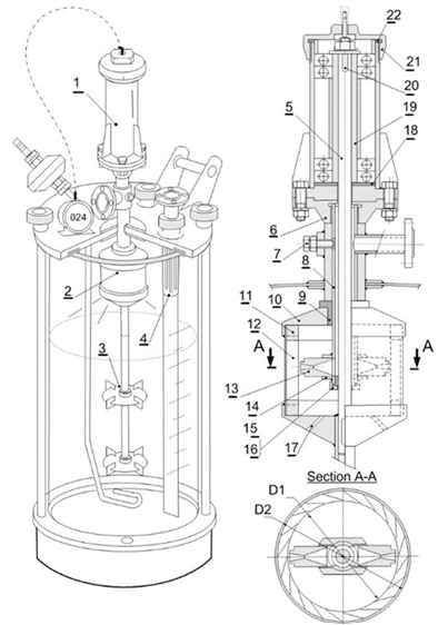
1-bearing housing 2-pneumatic device 3-mixing impeller 4-gas-outlet 5-impeller-shaft 6-screwing flange 7- assembling bolt 8-feed tube 9-oclussion 10-upper cap 11-groove element 12-vane 13-Laval nozzle 14-nozzle keeper 15-lower cap 16-steady bearing 17- gas outlet 18- compression gasket 19-constrained tube 20-ball bearing 21-outer cap 22-compression gasket.
Maximum Flow Rate: Constraint
A maximum air flow to the air expansion is assumed from practical experience and single-tube with three outlet orifices over the liquid surface in five-liters vessel (3mm diameter; 120°each); a rough value to observations,
3 20 t Q m hr = .(N) is measured and accepted to references of this job and maximum flow-rate to the power input, consequently G-reactor is constrained to maximum power rates, / 0.015 0.340 / w liq P V W liter = − approximately in agreement with (Table 2) and the strong-mild agitation regime from (Table1), [5] for the complete-rapid gas dispersion at gas-liquid systems; [1] to comparisons, common transfer rates to aerobic fermentations are ensured to power inputs, 0.098-0.493W/liter [2].
| HP/liter (up to) | W/liter(up to) | |
|---|---|---|
| Weak | 1.26 x10⁻⁴ | 0.095 |
| Mild | 2.34 x 10⁻⁴ | 0.191 |
| Strong | 6.44 x10⁻⁴ | 0.485 |
| Very strong | > 6.44 x 10⁻⁴ | > 0.485 |
Table 1: Agitation level. Stirrer tanks. (Only to references).
Mathematical algorithm: Example
The consumption parameters of G-reactor are estimated to specific process of liquid volume, ( 150 liq V liter = 1.25 ves liq V V = , non-standard vessel of geometrical rates
1 2 3.4, 1.0 x x = = ; six-flat-blade turbine impeller, four baffles each 0.1Dv broth density,
3 1200 / liq kg m ρ = , the viscosity, ( ) 0.0012 / , 1.2 kg m s cp µ = − , the working air-pressure and temperature
2 1 1 4.37 / , 300 P kg cm T K = = ; Chamber pressure, 2 2 1.50 / P kg cm = , Laval-nozzle throat diameter, 2.50 o d mm = ; number of vanes, Np=36; pneumatic device diameter, (tubes, DIN-2448),
2 7.0 0.219 167 D X inch mm = = ; rate 2 1 / 1.05 D D = ; the aeration-rate, ( ) 50 ./ g Q lit min N = ; friction and impact losses, 1 2 0.75 k k = = . A logical sense at calculations is shown. Geometrical rates: The geometrical rates are given to the expressions [3]
1_x_ Dv dag = . (4.1.1)
2 2 x H Dv = (4.1.2) The rate values, 1 2 3.0; 1.0 x x = = constitutes the reactor standard; conveniently it is assumed to the example,
1 2 3.4; 1.0 x x = = the liquid volume is obtained to the equation, ( ) 2 2 . 4 liq V H Dv π = (4.1.3)
After introduce the rate, x2 and transformation,
3 2 4. liq Dv V x π = (4.1.4) The vessel diameter is found ( ) ( ) ( ) ( ) 4 150 0.001 1.0 3.1416 0.333 0.575 Dv m = = To the previous assumption of geometrical rates, the remainder dimensions may be found, ( ) ( ) 2 0.575 / 3.4 0.169 0.575 1.0 0.575 1.25 0.575 0.717 dag m H m Hves m ≈ ≈ = = = = The total reactor capacity is found approximately ( ) , 1.25 1.25 150 190 . Vves Vliq liter ≈ ≈ = Impeller system: The number of turbine impellers is estimated from the arithmetic rule, 2 2 2 H dag dag Ni H dag dag − > > − Substituting values, ( ) ( ) ( ) 0.575 0.169 0.169 0.575 2 0.169 0.169 Ni − > > −
2.4 1.4 Ni > > ; The number of impellers is accepted, Ni=2 Ejection speed Laval nozzle: The specific gas-volume to the nozzle inlet,
1 1 2 . v R T T = . (4.3.1)
After substitutions,
( ) ( )
4 3 1 287 300 4.37 9.81 10 0.2008 E m Kg ν = =
Design tip: The gas velocity, Co in adiabatic expansion from
1 2 , Pto P increases to maximum critical value, cr C to the narrowest cross-section (nozzle throat), the mass flow-rate reaches a maximum constant-value, Qmas and the gas- pressure is critical, cr P ; higher values to cr C may be reached to a further expansion in divergent-convergent nozzles (Laval nozzle) only if cr P 2 cr P P > , that is, Case ( ) 2 cr P P > and Laval nozzle, o cr C C >= ( ) 2 cr Case P P < and Laval nozzle, o cr C C < The critical pressure, cr P at the equation, ( )
1 1 2 1 k k cr P P k + = + (4.3.2)
For the adiabatic constant of air, k=1.4 and substitutions, the foregoing equation reduces, 1 0.528 cr P P = ( )
2 0.528 4.37 2.30 cr P kg cm = =
The gas-velocity in expansion at every cross-section along the nozzle is given by,
1 2 1 1. 1 1 2 1 . 1
k k − = − −
o P C k k k P v P
( )
1 0.75 k = The friction loss factor is assumed at calculations, ( )( )( )( ) ( ) ( ) ( ) 0.75 2 3.5 4.37 9.81 4 0.2008 1 1.50 / 4.37 0,2857 0.5 o C E = −
298.7 / o C m s = To the nozzle throat, ( )( )( )( ) ( ) ( ) ( ) 0.75 2 3.5 4.37 9.81 4 0.2008 1 2.30 / 4.37 0.2857 0.5 c C E =
237.5 / c C m s = The specific air-volume to the nozzle outlet ( )
1 2 1 1 k v v P P = (4.3.4)
Where it is fulfilled to the Eq. (4.3.4),
( ) 2 ; cr cr Case P P then P P >= =
( ) 2 2 ; cr Case P P then P P < =
To substitutions
( ) 3 2 0.2008 4.37 / 2.30 0.7143 0.3176 / m Kg ν = =
Mass flow rate: The mass of the air flow is obtained to the expression,
2 2 . . 4 mas o o Q d C v π = (4.4.1)
( ) ( ) ( ) 0.0025 2 237.5 4 0.3176 0.00367 / mas Q Kg s π = =
13.21 mas Q Kg s = To the assumption of isotropic expansion the air temperature may be estimated, ( )
1 2 1 2 1 k k T T P P − = (4.4.2)
( ) 2 300 1.50 / 4.37 0.2857 221 51 o T k C = ≈ ≈
Volumetric air flow: The total volumetric air-flow at the operation, . t mas Q Nn Q air ρ = . (4.5.1) For the air density ( ) 3 3 , 1.29 / 1.033 / , 0 o air kg m kg cm C ρ = it is found, ( ) ( ) 3 2 0.00367 /1. 29 0.0056 / t Q m s N = = ( ) 3 20.48 / . t Q m hr N = (near result to the constrained value) Reactive force: High speed values to the gas ejection may increase the reactive force by the product, . re mas o F Q C = (4.6.1)
After substitutions
( ) 0.00367 298.7 1.096 re F N = =
Design tip: Similar magnitude of the reactive force may result from large-small nozzles indistinctly, namely the smaller ejection speed and differential pressure to high air- flow rates in nozzles of large diameters and conversely.
Resultant torque:
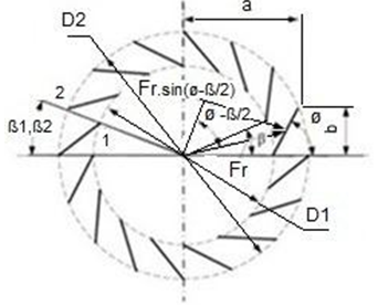
G-reactor increases the power-input to high speed values of the air jet at the expansion and both nozzles, a pair of forces and the momentum to the rotational motion takes place; the expression at torque calculations may be found from the sketch (Figure 2).
( ) 2 1 2 1 . . . 2 sin 2 t mas o M k Np Q C D D D β φ = + − − (4.7.1) The variables at the expression are found,
360 Np β = (4.7.2) ( )
0 360 / 36 10 0.175_rad_ β = = =
( ) 2 2 cos a D β = (4.7.3)
( ) ( ) 0.167 2 cos 10 0.082 a m = = (4.7.4) ( ) 2 2 sin b D β =
( ) ( ) 0.167 / 2 10 0.014 b sin m = =
( ) 1 tan 2 b D D φ α = − (4.7.5) ( ) ( ) ( ) 1 1 0 0.014 / 0.082 0.159 2 5.6 79.80 tan tan φ − − = − = =
1 2 1.05 0.167 1.05 0.159 D D m = = = (data example) The impact and friction loss factor is assumed to the air-jet,
2 0.75 k = and to substitutions into Eq. (4.7.1)
( )( )( ) ( ) ( ) ( ) 0.75 36 0.00367 298.7 0.159 0.167 0.159 2 sin 79.8 10 2 t M = + − − 4.65 t M N m = −
Power Input: Mixing Impellers
The equation at power calculation of impellers comes from the dimensional analysis and the study of models, resulting the graphic data correlation of power number, Kn versus Reynolds number, Re and the well-known calculus expressions [6].
3 5 . . . w liq P Kn n dag ρ = . (4.8.1)
2 . . e liq R n dag ρ µ = . (4.8.2)
The correction factor, fo, should be introduced at power calculation of impellers if geometrical rates deviate from the standard. (Represented by *) [3].
| Dv dag*(H dag)* Dv dag (H Dv) 2 2 | Ni 1 |
|---|
From the data example( ) 1 2 3.4; 1.0 x x = = and substitutions ( )( ) ( )( ) ( ) ( ) 0.5 0.5 , 3.4 1.0 / 3.0 1.0 2 /1 1.50 of = = The power input to immersed impellers at gas-liquid systems decrease and the aeration factor, fg should be introduced to the final calculus expression,
3 5 . . . . . w liq o g P Kn n dag f f ρ = (4.8.4)
Design tip: The aeration factor, / g g w f P P = is less than unity and it is smaller to lower multiple impellers under direct influence of the gas hold-up, however from the small differences depreciated in small reactors, a constant aeration factor is assumed [1].
Impeller speed: Un-gassed systems Design tip: The power of a body at uniform rotational motion and the respective units of angular speed ( ) rad s ω and the resultant torque ( ) t M N m − is given to the expression, . w t P M ω = (4.9.1) To prime mover conditions at imminent motion and from the Newton laws, both equations (4.8.4) and (4.9.1) may be equaled introducing the term 2π to units compatibility, arriving to the calculus expression for the speed developed by the pneumatic device and the impeller system.
5 2 . . . . . t liq o g n M Kn dag f f π ρ = (4.9.2)
To a system of turbine impellers at the example and the assumption of turbulent agitation regime to Reynolds over 104 and the un-gassed mixing conditions, it is found, ( ) 1.0 gf = it is found, 6.20 Kn = To substitutions, ( )( ) ( )( ) ( )( ) ( )
0.5 5 2 3.14 4.6556 6.20 1200 0.169 1.50 1.0 n =
4.36 261.6 n rps rpm = =
Power Input: Un-Gassed Systems To the assumption of Reynolds over ( ) 4 10 , 1.0 gf = and the previous speed value, the power input to un-gassed systems is obtained to substitutions into Eq. (4.8.4) ( )( ) ( ) ( )( ) 6.20 1200 4.36 3 0.169 5 1.50 1.0 127.5 w P W = = And the power-rate becomes,
127.5 150 0.85 w liq P V W lit = = . (To the strong agitation regime at Table1) To verifications the Reynolds number is found, ( ) ( ) 4.36 0.169 2 1200 0.0012 124525 e R = = The result demonstrates the previous assumption is correct, i.e., the turbulent agitation regime to un-gassed systems is confirmed. ( ) 6.20 Kn = Oxygen supply: Actual rate The aeration rate at the example, g Q is given to standard conditions, 50 min g Q lit = (N) ( ) 2 0 1.033 ,0 kg cm C thus, the conversion to actual working conditions, ac Q is obtained applying the gas laws and absolute pressure values.
0 . 273 1.033 273 b ac g P Q C Q + = . (4.11.1) The actual pressure to the air sparger location under the lower impeller near the vessel bottom is evaluated from the pressure-head plus the hydrostatic pressure.
( ) 2 2 bP P H dag γ = + − . (4.11.2) The working conditions at the reactor chamber are known from the data example,
2 0 2 1.50 ,21 P kg cm C = After substitutions, ( ) 2 1.50 1200 0.575 0.169 10 4 1.50 0.0487 1.54 / bP kg cm = + − − = + = ( ) 2 2.54 / bP kg cm abs = The actual aeration rate ac Q is found to the Eq. (4.11.1) ( )( ) ( ) ( ) 1.033 50 273 21 2.54 273 21.9 0.15 ac Q lit min vvm ≈ = + Design tip: Mechanical breaks of the sparging gas near the lower impeller into small air-bubbles improve the oxygen transfer with a significant reduction to the power input at the influence on the liquid density.
Power input: Gassed systems The air flow rate to actual working conditions is already known 3 21.9 0.00037 / ac Q lit min m s = = and the Aeration number is found from the equation, [1]
3 . ac Na Q n dag = (4.12.1)
( )( ) 0.00037 4.36 0.169 3 0.017 Na = =
The graphic data correlation of aeration factors, gf versus the Aeration number, Na is reported [1]. From 0.017 Na = , the aeration factor result, 0.74 gf ≈ and the power input at gassed systems is calculated ( ) ( ) 0.74 127.51 94.3 g g w P f P W = = = The power rate is obtained, 94.3 150 0.63 w liq P V w liter = = , Showing a reduction around the thirty, 30% percent to the aerobic processes.
Structural strength:
The impeller system should withstand the bending and torsion moments caused by the hydraulic forces over the impeller shaft in cantilever (the shaft without support at the vessel bottom); the typical analysis of structural strength obtains the minimum shaft-diameter (Section Modulus) to support the combination of tensile and shear-stress from the forces and moments; by the other hand, to prevent the collapse of the impeller system, the natural frequency should be known beforehand to avoid near operations which can be modified conveniently adding/subtracting weights.
The calculus expressions of Moments for individual impellers are shown for comprehension (Figure 3).
( ) . t c w M f P n Ni =∑ (4.13.1)
9.55 cf = (conversion factor) ( ) . . . f c w M f P L n Ni dag =∑ (4.13.2)
2.88 cf = (conversion factor) To substitutions, ( ) ( ) ( ) ( ) 2 127.51 2 261.6 2 232.7 4.65 t c M f N m = = = − ( )( ) ( ) ( ) 127.51 2 261.6 0.169 0.47 0.21 2.82 f M N m = − = − The energy The power consumption to the adiabatic compression, ( ) ( ) ( ) . . 1 1 1 w c t f o CP f Q k k P P k = − − − (4.14.1) Where, cf conversion factor 7 2.87. 10− = ( )( )( )( ) ( ) ( ) 20.48 3.5 1.0 9.81.104 4.37 1.0 0.2857 1 w c CP f = −
1.06 w w CP K hr =
Scale-up: Descriptive Data analysis
The software in C# provides comparative results of the reactor performance to changes of geometrical rates, the impeller speed and the mix-liquid properties to the assumption of low-viscosity Newtonian fluids and systems of geometric and dynamic similitude. G-reactor is constrained to maximum air flow-rate to the power input by self-design, 3 20 / t Q m hr = . (Normal) consequently the consumption values at the scale-up are found to trial and error and the maximum value; the calculus reiterations of strong influence factors to the power input may lead to the maximum reactor-scale from, 100 150 liq V liter = ÷ and the technical specifications at data shown on (Table 2).
| G-reactor | Broth data example | Water un- gassed | |||
|---|---|---|---|---|---|
| un gassed; f = 1. 51 o | gassed, f = 0. 74 (0.15vvm) g | ||||
| P (kg cm2) 1 | 4.38 | 4.3 | 3.56 | 3.5 | 3.79 |
| Q (m 3 hr .,N) t | 20.6 | 20.2 | 16.7 | 16.5 | 17.8 |
| n ( rpm) | 260.2 | 230.2 | 260.2 | 230.2 | 230.2 |
| P (W) w | 127.1 | 109.5 | 94.1 | 81 | 91.2 |
| M (N −m) t | 4.67 | 4.54 | 3.45 | 3.36 | 3.89 |
| CP (k /hr.) w w | 1.06 | 1.03 | 0.72 | 0.7 | 0.81 |
| P /V (W lit) w liq | 0.85 | 0.73 | 0.63 | 0.54 | 0.61 |
| Re ( - ) | 124E3 | 141E3 | 124E3 | 141E3 | 141E3 |
geometry in blue, ( ) 1 2 150 1.25 ; 3.0, 1.0 liq ves liq V liter V V x x = ≈ = = The consumption parameters of G-reactor to the Scale- Down and frequent regime of mild agitation of biochemical processes are shown at (Table 3) (n<<260rpm; n=150rpm) using water to comparisons. Note that the power input is proportional to the impeller-speed raised 3 to the calculus expression and the marked reduction of the data shown occur. (eq. 4.8.4) The sketch of G-reactor from the data example is shown (Figure 3).
| G-reactor | Broth data example | Water un- gassed | |||
|---|---|---|---|---|---|
| un gassed; f =1.51 o | gassed, f =0.74 (0.15vvm) g | ||||
| P (kg /cm2) 1 | 2.3 | 2.53 | 1.97 | 2.15 | 2.34 |
| Q (m 3 hr ,N) t | 10.43 | 11.8 | 8.03 | 9.42 | 10.7 |
| n (rpm) | 150.2 | 150.2 | 150.2 | 150.2 | 150.2 |
| P (W) w | 24.5 | 30.4 | 15.2 | 20.4 | 25.3 |
| M (N −m) t | 1.56 | 1.93 | 0.96 | 1.43 | 1.61 |
| CP (k /hr.) w w | 0.28 | 0.35 | 0.17 | 0.25 | 0.29 |
| P /V (W /lit) w liq | 0.16 | 0.21 | 0.1 | 0.14 | 0.17 |
| Re ( - ) | 716E2 | 920E2 | 716E2 | 920E2 | 920E2 |
( ) 1 2 150 1.25 ; 3.0, 1.0 liq ves liq V liter V V x x = ≈ = = Among factors of strong influences to the power input the core-diameter to increments up to 2 , 7.0 D = inch (tubes, DIN2448) at this job, the number of vanes, Np=36, the changes of geometrical rates, 1 2 , x x , etc.; (Figure 1) rational non-contradictory results are obtained to the overall energy loss factor, 1 2 * 0.56 t K k k = = on the author opinion, such as the power rates to strong-mild agitation regime at (Table1), the impeller speed, the air-pressure and the energy; to generalizations at program runs it is found, the weak influence to the power input to changes of the broth properties (eq.4.8.4) and the significant reduction around the thirty percent, 30% at gassed system/aerobic processes
0.15 ; 0. 4) ( 7 ac g Q vvm f ≈ = ; (Table 2 & 3).
Micro-Plants: Sterile Air
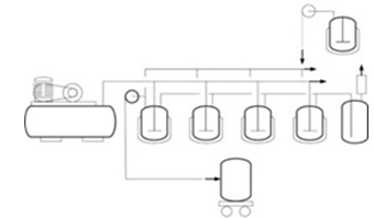
The air to high temperatures and pressure at compression keeps the capacity of absorption and retention of water to the vapour-stage and it should be refrigerated and dried in order to eliminate condensations; about the air quality and those parameters to regulations and control, e.g., the air-pressure and temperature, wet content, microbial population, rare particles on suspensions, etc. The next technical description of micro-plants and the production of dry sterile air may lead to the process engineering and the preliminary analysis of costs [4].
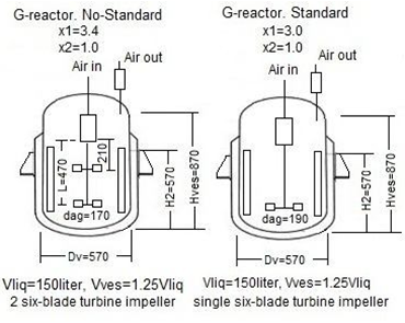
Figure 4: Scheme of micro-plants. Micro-plant layouts distinguish by a single compression unit at the production of dry sterile air to the power input and small installations of stainless steel tubes for compressed air and the transport of fluids at services with the available overall automatic flow control; (Figure 4) common procedures on cleaning and sterilization may apply, e.g. swept of dry air to eliminate possible condensate remainders, water steam, chemicals, etc.
Alternative Compressors
The alternative compressors show important technical profits to the use, maintenance and sale offers, becoming the best choice for the industry and services frequently; the air to the oil-free alternative compressors is certificated for the pharmaceutical industry, foods, chemistry and labs, etc.; the equipment specifications show outlet temperatures of 130C0 and 80C0 to alternative and rotary compressors and water contents depending the temperature and pressure to saturation conditions, e.g.10g/m3, 4.0kg/cm2(abs), 30C0. The oil-free alternative compressors and the next technical specifications are recommended for micro-plants.
( ) 2 1 1.02 / bar kg cm =
• Single-stroke, single-stage, air cooling; capacity: up to
3 1.0 / . m min (N), 8 bar • Single-stroke, two-stage, air cooling; capacity from
3 1 10 / . m min − (N), 8 bar
Water Cooling
The refrigeration of the air takes place from 130C0 up to 30-35C0 approximately to arrangements of tubes usually of copper and water cooling on heat-exchangers, eliminating approximately the 80% of condensates by the siphon method; the heat-transfer by forced convention induced by fans may be employed to certain conditions and small compression units; to multi-stage compressors (two or more) the refrigeration takes place between compression- stages and similar systems integrated to the air-compressor itself; the remaining water content is eliminated completely on the drying systems.
Drying Systems
Two systems are described briefly, those using absorbent materials such as the alumina and the frigorific systems respectively; dew-points up to -20C0 may be reached to the absorption methods where later condensations at practical conditions should not occur; the air refrigeration to the frigorific systems takes place up to 3C0 approximately and the latter heating from the yield heat at service pressure, showing low-costs and simple maintenances, e.g. the typical commercial Freon-based refrigerated compressed air dryer.
Distribution Tank
The air-compressors works to the cyclic operation regime and a distribution tank in order to warrant the air service on the resting times, otherwise the air compressors should work to continuous regime in agreement with the technical specifications, operation regime, plant schedule and maintenances, etc.; the service pressure should overcome the estimated values at design time around 0.1 0.2 ÷ bar approximately and the small installations.
Prophylaxis
The prophylaxis treatment of the outlet gas-flow to positive gauge pressure is proposed by continuous gas- sparging into bactericides with the purpose of killing noxious micro-organisms on suspension; regarding the agitation degree resulting, the small tanks for gas treatment of individual reactors is recommended, for example tanks of two, 2.0cubic- meter to sparging at mild agitation regime approximately the maximum flow-rate, ( ) 3 20 t Q m hr N = [7].
Conclusion
The author agree with rational non-contradictory results of the data shown to primary evaluations of G-reactor at Micro-plant and conclusions; in compliance with the assumed capacity to oil-free alternative compressors, (Chapter 5) the author proposes layouts of fifty, 50 reactors at micro-plants to references purposes, the capacity 7.5cubic-meters and the batch process, 150liters for the small production scale of drugs and the unit operations of the chemical industry.
Scheme of fifty, 50 reactors (Table 3)
Model: G-reactor, 150 liq V liter = : 1.25 ( ) ves liq V V = ;
Standard geometry, 1 2 3.0; 1.0, x x = = single turbine impeller six-blade, four baffles each, 0.1Dves) Micro-plant capacity: 3 7.5_m_ Oil-free alternative compressor:
3 1 10 / , m min − 8 bar (abs) Working air-pressure, 2 1 0 2.53 / P kg cm = ÷ (start-up) Working air-pressure, 2 1 0 2.15 / P kg cm = ÷ (steady regime) Impeller speed: 0-150rpm Power-rate, Air consumption:
3 3 50 *9.42 / . 7.85 / t Q reactors m hr m min = =
Energy: 50 *0.25 12.5 / . w CP reactors kW hr = =
Nowadays the mankind is facing to new viruses and dangerous bacteria that claim to new developments of drugs and researches; the author hopes is that G-reactor at micro- plant may contribute in some way at this goal and encourages the reactor construction which should be submitted to the standards of pressure vessels and the pharmaceutical industry, practical essays and the process validations; worthy of mention the pneumatic systems show low typical efficiency values (energy conversion) that is compensated commonly by the technical profits, the investment and the assigned service.
References
-
Hicks W, Gates E (1976) How to select turbine impellers for dispersing gas into liquids, Chemical Engineering (7):141-148.
-
Charles M (1975) Bioreactor Design, Operation and Control, Lehigh University, USA.
-
Aiba S, Humphrey AE (1973) Biochemical Engineering, first edition, Japan.
-
Sabras FS (1991) Guía Práctica Compresores ABC, Editorial EUHASA, España.
-
Ocon J, Vian A (1977) Elementos de Ingeniería Química, Edición española.
-
Rushton JH, Costich EW, Everret HJ (1950) Power characteristics of mixing impellers, Chemical Engineering Progress (46): 467-476.
-
Herber W, Cooper A (1963) Area allocation for distributor pipes, Chemical Engineering, New York.
- Acido Labile or Gastro Irritant Apis and Enteric Release in Galenic Practice: An Overview
- A Study on Knowledge, Attitude and Practice of Hand Hygiene among Healthcare Professionals at a Tertiary Care Hospital, India
- Influence of Inoculum Concentration on In Vivo Incubation Period of Emmia lacerata, Pathogenesis and Management of Wilt in Pepper (Capsicum annuum L.)
- Vanilla’s Chemistry
- Marine Anti-Cancer Compounds and Adverse Effects of Global Warming on Oceans: An Overview
- Serological Investigation of Chikungunya Virus Antibody among Malaria-Suspected Febrile Patients in Some Healthcare Facilities in Rivers State